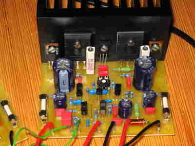
Good quality design, a nice amplifier circuit has all the details (in English) Scope measurements, pcb and voltage values are specified, there is an additional circuit diagram. The Symasym5 is a power amplifier designed with quality yet low price in mind. This resulted in a Class AB BJT amplifier using only TO92 transistors for input and VAS with a reasonable number of parts. The topology used is well known and consists of a single diffamp for input and a 2nd diffamp with valid mirrors for the VAS.
This is followed by the normal darlington EF output stage using modern high beta devices. The circuit uses large amounts of feedback over the entire audio band and an unconventional feedback compensation scheme.
Currently symasym is designed to be run directly from a CD/DVD player, simply insert a 22k poslog stereo pot between the player and symasym. (as voltage divider)


Symasym Features:
THD: ~0.005% (measured) simulation: 0.002%
Power to 8ohm: 60 watts
Power to 4ohm: 100 watts
Gain: 32dB (~1:40) full output at 0.7v input (0.5v rms)
Feedback: 57dB
Phase margin: > 90°
Supply voltage: +/- 36v
Bias: 55ma, 12.1mv through a single 0.22 ohm
Measurements: RMAA Symasym5_2 Measurements are far from perfect, but give a good idea!
Frequency response: 3.2hz to 145khz (-1db) using 4.7uf input cap
Phase shift at 10khz: 3°
More will follow!
Sound: Great dynamics, very tight and controlled bass, surprisingly detailed sound, a colorless and incredible soundstage! Also, the on/off sound is not recognizable. The sound image is striking, tactile, completely intelligible. The sound is pleasant, not bright/false highs, almost soft but very transparent. Symasym does not prefer special music genres, it plays all kinds of music with signals or DVDs without any problems.
Recommended parts: All resistors are standard metal film 250mW except the following: R1/3/4/7, these are 2W metal film and 0.22ohm 5W. An insulated (enamelled) copper wire of 0.6 mm is wound around R7, forming the output coil. I used 470uf/16v for c19 and 63v for all other electrolytics. Must be 22/100/330pF mica cap. 100nf and 47nf are recommended to be Wima MKS2, also for C1, I recommend Wima MKS2, 4.7uf is enough.
I use Piher for trimpot. MPSA18 is interchangeable with BC550C, for all other parts I do not recommend modification, especially feedback network should be kept unchanged, feedback compensation is very sensitive for this circuit! Be careful when replacing MPSA18 with BC550C, the pinout is reversed between these 2 transistors!!!

Source: www.lf-pro.net/mbittner/Sym5_Webpage/symasym5.html 100W Hi-fi AmplifierCircuit symasym pcb schematic alternative link:


Brushed Motor ESC PIC12F675 PWM
Brushed Motor The Microchip 12F675 offers a number of interesting facilities that are used in this design. These facilities permit a much better ESC to be designed than is possible with a 12C5xx PIC, without the complexity of designs using larger PICs. Most standard ESCs convert the throttle setting into PWM rates using a simple linear mapping. So that 50% throttle corresponds to a 50% PWM. However, a 50% PWM rate is actually delivering only 25% of the full power to the motor. This is the standard configuration of this ESC also.
PWM Brushed Motor ESC