There are asm hex schematic pcb files, the coil windings are illustrated, the supply voltage and the power vary according to the transistors used. Values between 1..7 watts are given. The transmitter includes optional pre-emphasized RDS/SCA input and Audio/MPX input. It can be used with or without a stereo encoder. Tuning over the FM band is provided by two buttons controlling the double speed PLL. The transmitter can also work without the LCD screen. Some experience with such building devices is highly recommended.
PLL FM Transmitter Circuit

Features
Supply voltage 11-13.8 V (stabilized or from battery)
supply current up to 1.2 A
standard frequency range 87.5-107.9 MHz
Audio/MPX input sensitivity 2 V pp (for 75 kHz frequency deviation)
RDS/SCA input sensitivity 0.2 V pp (for 7.5 kHz frequency deviation)
Panel dimensions 109x54mm
A 0.05 MHz tuning step and a 3.2 MHz crystal are required. In other cases, a 6.4 MHz crystal will do fine (tuning step 0.1 MHz). No other crystals can be used. Wrap all coils (except L2) with 0.8 mm wire. Y1 pack must be connected to ground! Make sure the Q3 terminals are as short as possible (about 2-3mm above the board). 2N3553 chassis/heatsink cannot be connected to ground! Be careful when soldering smd capacitors!
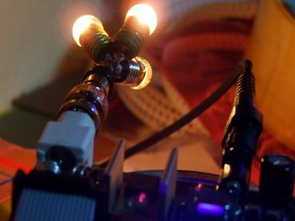
After the placement of the parts is complete: Check that there are no shorts bridging adjacent pallets or pads. Check the polarity of the electrolytic capacitors and the orientation of the semiconductor parts. Do any duty load and temporarily connect it to the antenna connector. For example use 2 or 3 bulbs (24V/170mA or 24V/3W) in parallel (see picture).
Start with a smaller power supply voltage, for example 9 V. The bulbs should light up a little. Then it’s ok and you can increase the power supply voltage to 12 V Set C18 to maximum output power (impedance set). Adjust the right LCD contrast with R23.
Now the L1 coil must be adjusted by stretching or tightening the turns. It affects the frequency position of the band that the PLL can tune. Set it to 107.9 MHz using the buttons. Measure the set voltage at collector Q4. Adjust the setting voltage to 7.5 V by adjusting L1. Then you’re done.
Now set it to 105 MHz and finally set C18 to maximum power. At this point, use about 10 meters of coaxial cable between the transmitter and the payload!
If you have a problem with stability/spurious oscillations (very unlikely if you used standard components and procedures), you can: reduce R7 or R9 increase R8 reduce power supply voltage use another material for TR1
If you want to change the output power, you can do so by changing the value of R8. Do not use smaller values than specified in the parts list!

Source: pira.cz PLL FM Transmitter pic assembly code schematic pcb alternative link:


Adjustable Bass Filter Circuit
Of a power amp bass amp filter circuit can be used in different times, in addition + – 60 + symmetrical voltage – 15 volts regulator circuit for limiting transistor has