Of a power amp bass amp filter circuit can be used in different times, in addition + – 60 + symmetrical voltage – 15 volts regulator circuit for limiting transistor has
The frequency of the filter cut-off regulated na is a stereo potentiometer P1. For acoustic applications, the filter does not it must be perfect and therefore it was possible use of a stereo potentiometer.
which unfortunately does not have a good one concurrency of both sections. A little bit corrects the fact that it is a potentiometer of which, by definition, always has a better one concurrency rather than a logarithm potentiometer.
In the falling part of the slope characteristics is 12 dB / oct. complement changeable filter is not a low-pass strobe filter implemented on the US2A operational amplifier. The frequency of cutting off this filter is about 150 Hz. The accidental characteristics both filters for different positions of the slider the potentiometer.
Regulation is subjective choosing the filter’s limiting frequency and the level of the signal reproduced by subwoofer. In principle, there is no general tips on how to follow the rules lacjach. The only thing that can be dealt with is regulation at average headroom Play music for different music recordings. It’s best to choose which recordings are well known (auscultated) then it will be easier to pick up the differences nice sound.

Bass Filter Circuit Schmeatic

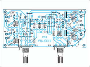
Bass Filter Circuit PCB schematic files;


TTL CMOS Databook Program
IC-Databook free handy catalog for 40 and 74 series integrated. program 230 has integrated information from the Edit menu additions you can make in the Datasheet and Directory partition information is stored in txt file