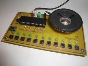
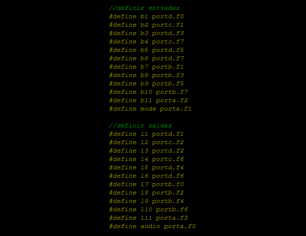
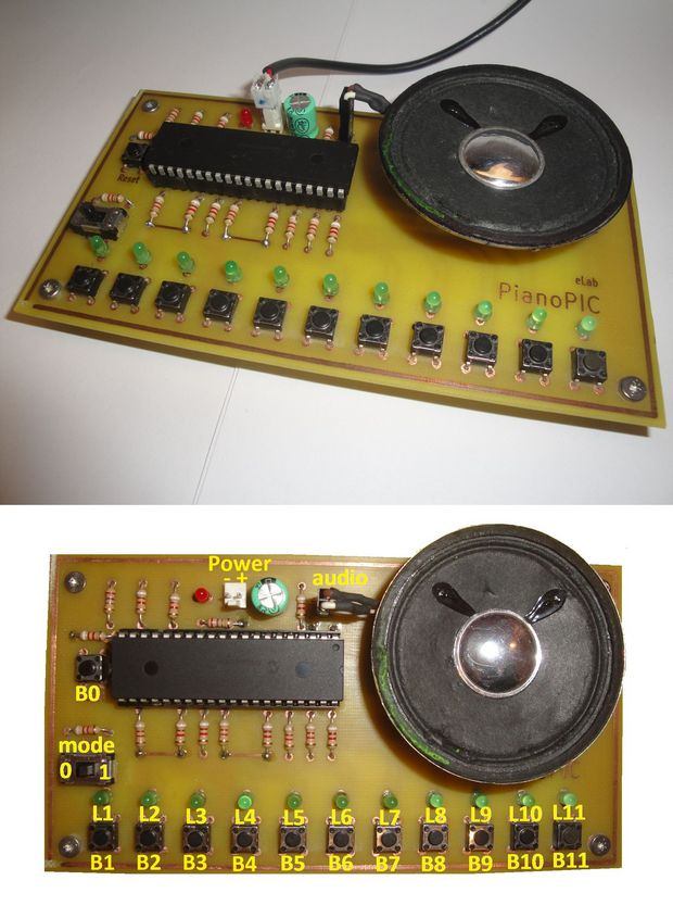
Electronic piano circuit PCB printed circuit board drawing upon the Pic18f4550 microcontroller PIC has been a regular speaker on the card directly to number 2 in the pin of this RA0-Pic18f4550 AN0 pine bjt, mosfet transistor or the amplifier can be increased by adding volume.
B1 …Each of the different frequencies of sound to piano buttons B11 to produce.
B1-LA (440 Hz)
B2-Sİ (494 Hz)
B3-DO2 (2X261Hz)
B4-RE2 (2X293Hz)
B5-Mİ2 (2X329Hz)
B6-FA2 (2X349Hz
B7-SOL2 (2X392Hz)
B8-LA2 (2X440Hz)
B9-Sİ2 (2X494Hz)
B10-DO4 (4X261Hz)
B11-RE4 (4X293Hz)
Crafted with only the software you don’t have source code mikroC hex, but given the information needed for sound Sound_Play library used mikroc
For example, B1 button;
Audio output 440 Hz square wave. To do this, 440 Hz duration 1/440 = approx 2272 mS equal to. After the delay (1136 mS) “1” output, and then exit the “0″, do (you can google translate minor errors with the statement that it will solve the situation inceleyinc the sample code mikroC people dealing with) each of them is used to produce different frequencies of sound.
if (b1)

{

audio=1;

delay_us(1136);

audio=0;

delay_us(1136);

}
source: ualgelab.wordpress.com/2013/03/09/pianopic/ alternative link:
FILE DOWNLOAD LINK LIST (in TXT format): LINKS-22711.zip


Pic16f877 With Bottle Filling System
In this article, and a student friend, talk about his work with a bottle filling machine from the block schema system easier.
Block diagram of bottle filling machine;
Elektronische Klavier Mit PIC-mikrocontroller
Elektronische Klavier Schaltung Leiterplatte Zeichnung auf dem Pic18f4550 mikrocontroller PIC wurde regelmäßig als Referent auf der Karte direkt zu Nummer 2 die pin dieser RA0-Pic18f4550 AN0 Kiefer-bjt, mosfet-transistor oder der Verstärker kann erhöht werden durch hinzufügen von Volumen.