You can use the LC meter circuit to measure the coil and capacitor values made with the PIC16F628 microcontroller. High precision Digital LC Meter A handy do-it-yourself test equipment – a Digital LC Meter for measuring inductance and capacitance over a wide range. It is based on an ingenious measuring technique, offers astonishing precision and is easy to construct.
Any digital multimeter has capacitance measurement ranges. Therefore, it is not difficult to measure the value of their capacitors as long as their value is more than about 50pF.
Below this level, digital multimeters are not very useful for capacitance measurements. Special digital capacitance meters are of course available and usually measure up to a few pF. However, they are also of limited use if you want to measure things like stray capacitance.
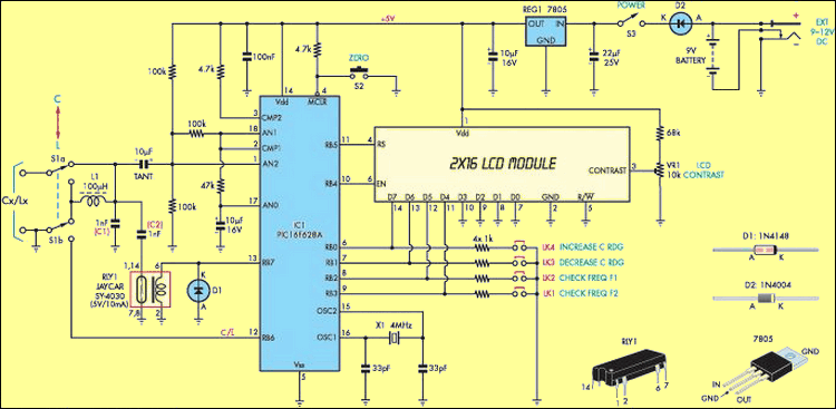
LC Meter Circuit Diagram
It’s even worse when it comes to gauge inducers. Few digital multimeters are capable of measuring inductance, so in many cases you will need to use an old-school inductance bridge or ‘Q’ meter. Both of these are basically analog devices and do not offer either high resolution or particularly high accuracy.
It’s different for professionals who have been using digital LCR meters for the past 20 years. These allow you to quickly and automatically measure almost any passive component, often measuring not only their primary parameters (such as inductance or capacitance) but also one or more secondary parameters. However, many of these beautiful instruments also carried a high price tag that was out of reach for many of us.
Fortunately, thanks to microcontroller technology, this has changed a bit over the past few years, with much more affordable digital tools now available. These include both commercial and DIY instruments along with the unit described here.
LC Meter Main Features
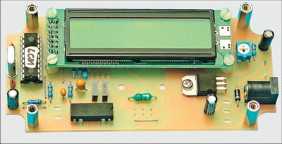
The Digital LC Meter device has a very compact design. Despite its low cost, it offers a wide range of automatic direct digital measurement for both capacitance (C) and inductance (L) in 4-digit resolution. In fact, it only measures capacitance from 0.1pF to 800nF and inductance from 10nH to 70mH. The measurement accuracy is also surprisingly good, better than ±1% of the reading.
It also operates on 9-12V DC and draws an average current of less than 20mA. Can be powered from a 9V alkaline battery or an external adapter (battery recommended)
The impressive performance of the LC Meter is due to an ingenious measuring technique developed nearly 10 years ago by Neil Hecht in Washington state, USA. It uses a large test oscillator that varies in frequency by connecting the unknown inductor or capacitor you are measuring.
The resulting frequency change is measured by the PIC16F628 microcontroller, which then calculates the component’s value and displays it directly in an LCD reading.
LCD Display LC meter circuit

Source: http://www.siliconchip.com.au/cms/A_110500/article.html
LC meter circuit PCB schematic pic16f628 pic assembly source code alternative link:


Balance Controlled Microphone Preamplifier Circuit (+3 Band Equaliser)
Circuit TL072 op-amp based on the second one 9 volt battery is fed with DC rectifier and regulator circuit on the 15 volt DC Adapter can be used with optional low noise, I suggest using the battery can not be over-current circuit
Hi,
Can anyone help me with this problem?: Include File “FP.TXT” not found
Where can I download the FP.TXT library?
Thank you
Hello,
The FP routines are in the separate file FP.TXT, which is taken from the MTI library file FP24.A16, but with the routines FLO1624 and INT2416 removed because they are not needed here.
https://ww1.microchip.com/downloads/aemDocuments/documents/MCU08/ApplicationNotes/ApplicationNotes/00575.pdf
https://github.com/latchdevel/AN575