
The circuit is fed with 9 volt batteries based on 2 tl072 op-amps. If desired, it can be used with a 15 volt DC Adapter on the DC rectification and regulated circuit. I recommend using a battery for low noise. The circuit does not draw much current.
Balanced Microphone Preamp Circuit
The rugged design includes a 3-band equalizer. It also has balanced and unbalanced outputs and can drive a stereo or guitar amplifier.
Microphone Preamp Circuit Main Features
Balanced input for microphone
Balanced and unbalanced output
Level control
3-band equalizer
battery indicator
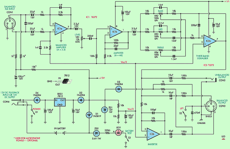
The circuit is based on two low cost op amp ICs: TL072 IC1a and IC2. The IC1a functions as an unbalanced preamplifier while the IC1b functions as a 46-gain non-inverting amplifier. IC2b provides the out-of-phase signal for pin 3, while IC2a, VR2, VR3, and VR4 make up the equalizer stage.
Whether for karaoke, public concert or a band, a microphone connection to an amplifier is a basic requirement. This Balanced Microphone Preamplifier includes a 3-band equalizer and can be used to drive a guitar amplifier, any stereo amplifier, or to provide an additional channel for a public address amplifier.
Balanced microphones are preferred because they prevent the spread of sound and noise into the sound system. A balanced microphone usually has a 3-wire cable that connects with XLR plugs and sockets.
XLR pin 1 is return or ground and the other two terminals (pins 2 and 3) are for signals. The signals are in anti-phase; In other words, when one row is positive, the other row oscillates the same amount of negative. Any hum collected along the cable is effectively canceled because the same level of hum is present on both signal lines.
XLR microphone preamp circuit diagram
Microphone Preamplifier of EQ

Source: http://www.siliconchip.com.au/cms/A_102159/article.html
Microphone Preamplifier PCB schematic alternative link:


Water Tank Level Indicator Circuit with LM3914
LM3914 integrates the general vu meter circuit showing on We hope this application `different does not count water tank level with LEDs designed to observe the control solid addition to for level detection ToS through the socket resistance group connecting the supply voltage 12 .18 v AC 1N4004 with a DC rectifier and 78L12 regulated by sections on
Water Tank Level LED Indicator