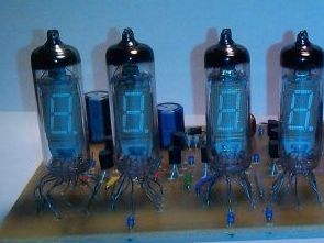
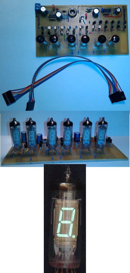
The project deals with the construction of a universal display panel with 6 8 segment display tubes (numitrons) IV-6 of Russian production. The panel is also supplemented with a control unit with Atmega32 processor, where software for realization of clock is implemented. The operation of the device is the same as with the classic digital clock (watch) using the MENU and SET buttons. In addition to the clock, additional sample “applications” are programmed as running text, ripples, or binary pointers to demonstrate display panel capabilities. In the future, there is an expansion of the program and control unit with microcontroller so that it is possible to numerically control FM tuner with PLL tuning or other HW peripherals. The panel can then display the current tuner frequency, the set radio alarm time as a classic clock radio and the like.
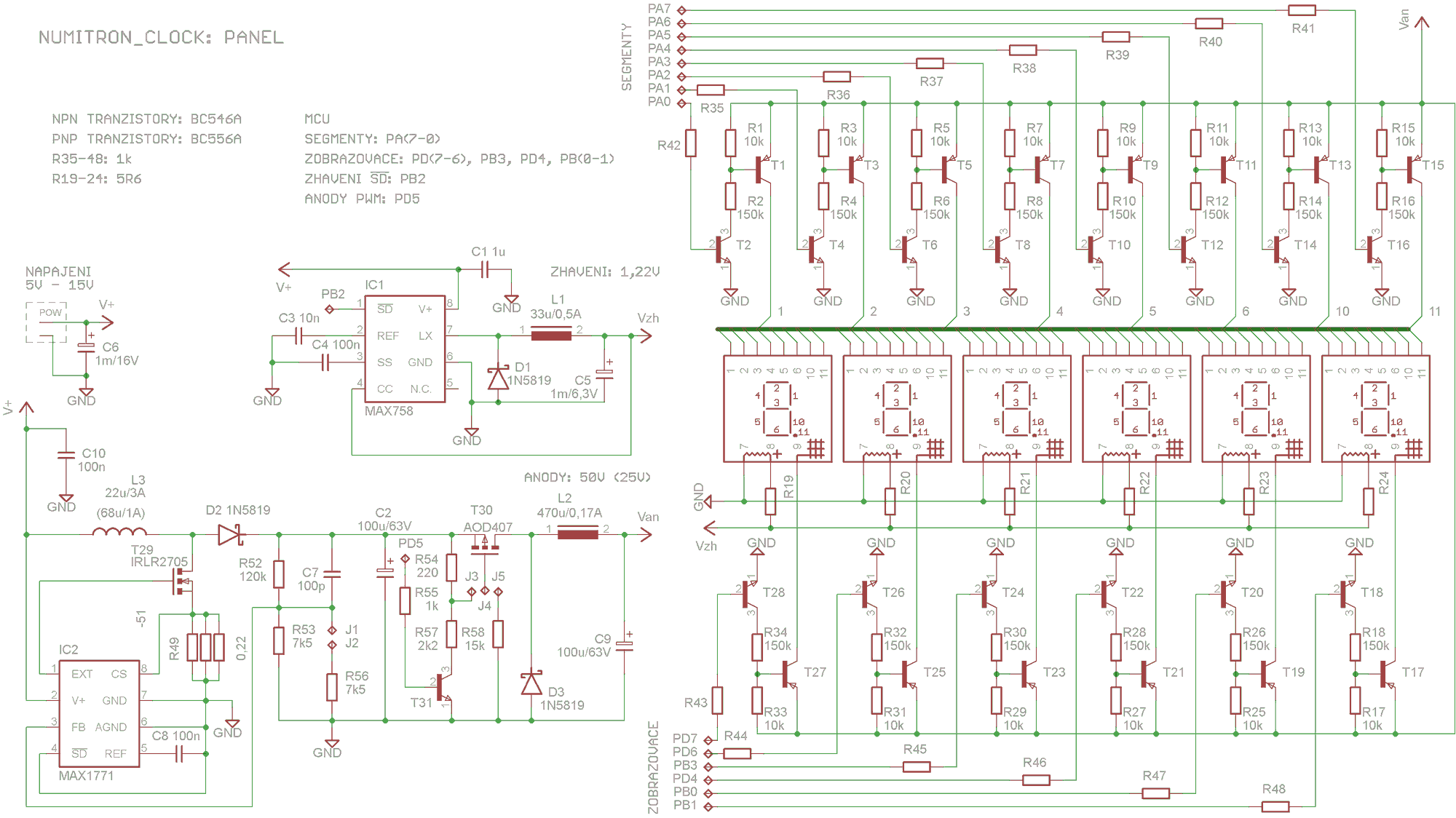
The display panel is implemented on a PCB that contains 6 pieces of numitrons themselves, transistors for multiplex control and 2 switched sources for powering the displays. The switching step-up power supply provides power to the display anodes with 25V / 50V output voltage selection depending on whether static or multiplex control is used and is supplemented by the possibility of external MAX1771 PWM control (resulting numitron light intensity). Another MAX758 step-down power supply provides a 1.22V voltage to power the numitron filaments. Both switching power supplies are implemented by Maxim integrated circuits, which were ordered as test samples. The resulting panel contains a power connector (input voltage is between 5V – 15V), 8-pin connector for single segment control and 8-pin connector for individual numitron switching, external PWM control and step-down control for glowing.
The control unit is realized on the contact field, it is just a processor with a crystal and buttons MENU and SET. References to the display panel wiring diagram, control unit, and complete technical documentation including source code are provided at the end.
Numitron clock circuit schematics

The whole program is written in one file for simplicity. The whole project from AVR studio can be downloaded at the end. The program described below is supplemented by additional menu items (“applications”). This is just a demonstration of the possible use of the display panel and their source code will not be further described.
The Atmega32 runs on a 14.7456 MHz crystal. The timer OC2 is used as the timer (it has the highest priority of interruption). The prefix is set to 256.
14745600 / (256 * 256) = 225
This means that OC2 is generated 225 times per second. These interruptions are computed by the time_cnt variable, when it counts 225 (exactly every second), the time_update variable is set to log1, and time_cnt starts counting from zero. The time_update variable is set until the time_init () procedure is initialized, then set to log0. The time_init () procedure runs from the main loop of the while (1) program just when the time_update variable is set to log1, which is approximately every second. Time is stored in the hr, min and sec variables by the time_init () procedure.
An OC0 counter is used for multiplexing. The prefix is set to 64.
14745600 / (256 * 64) = 900
OC0 is generated 900 times per second. Each interruption changes the mpx_state variable. It defines which of the 6 displays should be active at that moment. 6 bars of interrupt must be performed to display 6 characters, so the resulting refresh rate is 150Hz. The mpx_state variable is processed by the switch switch (mpx_state) in the main loop of the while (1) program so that the previous numitron turns off based on its state, turns on the current numitron and sends the required symbol to it.
DISPLAY PRINCIPLE
The values (characters) to be displayed on each numitron are stored in the digit_1 to digit_6 variables. These variables must be built with the switch (menu_state) in the main loop of the while program (1) before each display. According to the current value in the menu_state variable, the appropriate menu_x () procedure is executed, which assigns the variables digit_1 to digit_6 one of the defined constants (character set definition). If you need to display any time component, the num_to_digit () function is used. The input parameter is a number representing seconds, tens of seconds, minute units, etc. The output of the function is one of the defined constants.
BUTTON OPERATION
Pressing the MENU button causes an interruption to change the value of the current menu display, the menu_state variable. Pressing the SET button causes an interrupt to set the set_update variable to log1. The set_update variable is set until the set_init () procedure is initialized in the while (1) main loop. This procedure, based on which menu is active, increments the appropriate variables (menu CLOCK SET – variable increment hr, menu BRIGHTNESS SETTING – increment of variable brigh_state, etc.).
BRIGHTNESS ADJUSTMENT
The HW PWM counter module OC1A is used for brightness control. It is a 16-bit counter, but it is set to 8bit PWM mode, so it works “8 bit” and uses only the lower 8 bits of OCR1AL from the OCR1A registry pair. The brightness is controlled by the brigh_state variable. The brigh_state variable is processed in the main loop of the while (1) switch by the switch (brigh_state), which assigns the appropriate value to the OCR1AL comparison register.
The final size of the whole program is 3230B (9.9% of Atmega32 processor) with disabled optimizations. It’s optimized with 2058B.
The initial idea was to control the multiplex using the time_cnt variable using the OC2 reader already set for timing control. At the interruption frequency of this counter 225Hz and for 6 numitrons, the resulting reversal frequency of the displays is 37.5Hz. This value was too low, the flicker was too noticeable and was distracting, so another counter (OC2) was used for muliplex.
The display is smooth even when displaying 15 “frames per second (waveform menu). The response to button operation is immediate and accurate, so the processor’s parameters in the configuration are sufficiently dimensioned for this application and the program can be further expanded.
Control unit consumption is 45mA for 5V supply voltage. The display panel at maximum brightness (for 50V anode voltage) is 750mA for 5V and 280mA for 12V supply voltage. For medium brightness (for anode voltage of 25V) it is 275mA for supply voltage 5V and 100mA for supply voltage 12V. The maximum total power of the device does not exceed 4W, so the whole device can be powered from the USB port of the computer (it counts on the output current of the USB 1A port).
FILE DOWNLOAD LINK LIST (in TXT format): LINKS-26179.zip


Operational Amplifier Tester Circuit
Operational Amplifier Tester Circuit
This wiring is a module that makes it easy and easy to distinguish good operational amplifiers from defective ones. The op amp tester is designed to test simple, double and quadruple operational amplifiers.
The wiring diagram of the opamp tester is shown in the schematic diagram. There are components in the tester that, together with the operational amplifier being tested, generate a multivibrator. If the opamp is good, the multivibrator oscillates, and the LEDs flash alternately. If the opamp is defective, no LED is on, or only one is on. In order to test simple double and quadruple operational amplifiers without complicated terminal switching, the operational amplifier tester has a total of seven identical multivibrator circuits with LEDs that are connected to each operational amplifier in each socket. operational amplifiers in DIP8 housings. These are, for example, types MAA741, TL061, TL071, TLO8I, TLC271, LF355. LF356, LF357, NE5534 and others opamps.
Circuit d’horloge Numitron avec Atmega32
Le projet porte sur la construction d’un panneau d’affichage universel avec 6 tubes d’affichage à 8 segments (numitrons) IV-6 de production russe. Le panneau est également complété par une unité de contrôle avec processeur Atmega32, où un logiciel de réalisation d’horloge est implémenté. Le fonctionnement de l’appareil est le même qu’avec l’horloge numérique classique (montre) à l’aide des touches MENU et SET. En plus de l’horloge, des exemples «d’applications» supplémentaires sont programmés en tant que texte en cours d’exécution, ondulations ou pointeurs binaires pour démontrer les capacités du panneau d’affichage. Dans le futur, il y a une extension du programme et de l’unité de contrôle avec microcontrôleur de sorte qu’il est possible de contrôler numériquement le tuner FM avec le réglage PLL ou d’autres périphériques HW. Le panneau peut alors afficher la fréquence actuelle du tuner, l’heure de l’alarme radio réglée comme un radio-réveil classique et similaires.