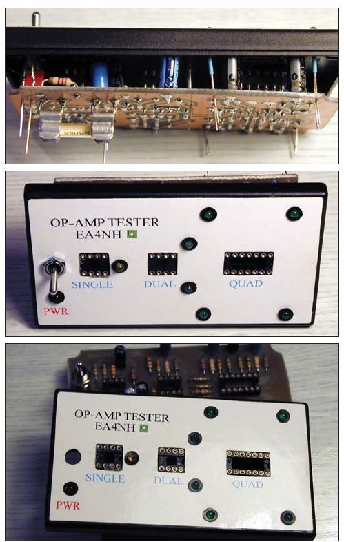
This wiring is a module that makes it easy and easy to distinguish good operational amplifiers from defective ones. The op amp tester is designed to test simple, double and quadruple operational amplifiers.
The wiring diagram of the opamp tester is shown in the schematic diagram. There are components in the tester that, together with the operational amplifier being tested, generate a multivibrator. If the opamp is good, the multivibrator oscillates, and the LEDs flash alternately. If the opamp is defective, no LED is on, or only one is on. In order to test simple double and quadruple operational amplifiers without complicated terminal switching, the operational amplifier tester has a total of seven identical multivibrator circuits with LEDs that are connected to each operational amplifier in each socket. operational amplifiers in DIP8 housings. These are, for example, types MAA741, TL061, TL071, TLO8I, TLC271, LF355. LF356, LF357, NE5534 and others opamps.
The respective LEDs are D1 and D2. At IO2, we can test double opamps in DIP8 housings. These are, for example, types MA1458, MC1458, LM358, TL062, TL072, TL082, TLC272, NE5532, CA3240 and others. The first operational amplifier indication LEDs are D3 and D4, the second D5 and D6. At I03 we can test quadruple operational amplifiers in DIL14 housings. These are the types BM324, LM324 TL064, TL074, TLO84, TLC274 and others. Multivibrator oscillations with the first operational amplifier indicate the LEDs D7 and D8, with the second D1 and D12 being the third D13 and D14 and the fourth D9 and D1O.
Op Amp Tester Circuit Schematic
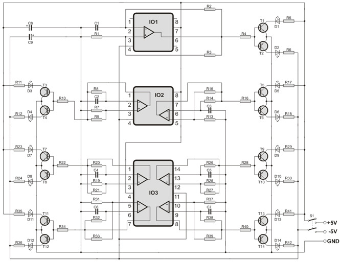
Supply voltage: ± 5 to 9V / 8OmA
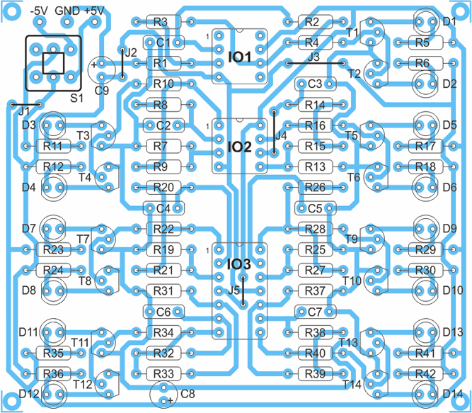
R1, R3, R7, R9, R13, R15, R19, R21, R25, R27, R31, R33, R37, R39 - 120k

R2, R8, R14, R20, R26, R32, R38 - 820k

R4, R10, R16, R22, R28, R34, R40 - 1k2

R5, R6, R11, R12, R17, R18, R23, R24, R29, R30, R35, R36, R41, R42 - 390R

C1, C2, C3, C4, C5, C6, C7 - 220n

C8, C9 - 1uf

D1, D2, D3, D4, D5, D6, D7, D8, D9, D10, D11, D12, D13, D14 - LED

T1, T3, T5, T7, T9, T11, T13 - KC237 (KC238, KC239)

T2, T4, T6, T8, T10, T12, T14 - KC307 (KC308, KC309)

Sleeve DIL8 - 2pcs

Sleeve DIL14 - 1pc

IO1 - simple operational amplifier (for example TL061, TL071, TL081)

IO2 - double opamp (for example TL062, TL072, TL072)

IO3 - quad opamp (eg TL064, TL074, TL084)

Switch - Two Position (L444)
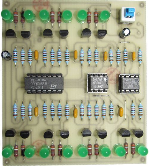
Operational Amplifier Tester Circuit 2
FILE DOWNLOAD LINK LIST (in TXT format): LINKS-26185.zip


Numitron clock circuit with Atmega32
Numitron clock circuit with Atmega32
The project deals with the construction of a universal display panel with 6 8 segment display tubes (numitrons) IV-6 of Russian production. The panel is also supplemented with a control unit with Atmega32 processor, where software for realization of clock is implemented. The operation of the device is the same as with the classic digital clock (watch) using the MENU and SET buttons. In addition to the clock, additional sample “applications” are programmed as running text, ripples, or binary pointers to demonstrate display panel capabilities. In the future, there is an expansion of the program and control unit with microcontroller so that it is possible to numerically control FM tuner with PLL tuning or other HW peripherals. The panel can then display the current tuner frequency, the set radio alarm time as a classic clock radio and the like.
The display panel is implemented on a PCB that contains 6 pieces of numitrons themselves, transistors for multiplex control and 2 switched sources for powering the displays. The switching step-up power supply provides power to the display anodes with 25V / 50V output voltage selection depending on whether static or multiplex control is used and is supplemented by the possibility of external MAX1771 PWM control (resulting numitron light intensity). Another MAX758 step-down power supply provides a 1.22V voltage to power the numitron filaments. Both switching power supplies are implemented by Maxim integrated circuits, which were ordered as test samples. The resulting panel contains a power connector (input voltage is between 5V – 15V), 8-pin connector for single segment control and 8-pin connector for individual numitron switching, external PWM control and step-down control for glowing.
Circuit de test d’amplificateur opérationnel
Ce câblage est un module qui permet de distinguer facilement et facilement les bons amplificateurs opérationnels des amplificateurs défectueux. Le testeur d’ampli op est conçu pour tester des amplificateurs opérationnels simples, doubles et quadruples.
Le schéma de câblage du testeur d’opamp est illustré dans le schéma. Il y a des composants dans le testeur qui, avec l’amplificateur opérationnel testé, génèrent un multivibrateur. Si l’ampli op est bon, le multivibrateur oscille et les LED clignotent alternativement. Si l’ampli-op est défectueux, aucune LED n’est allumée ou une seule est allumée. Afin de tester des amplificateurs opérationnels simples doubles et quadruples sans commutation de terminal compliquée, le testeur d’amplificateur opérationnel dispose d’un total de sept circuits multivibrateurs identiques avec des LED qui sont connectés à chaque amplificateur opérationnel dans chaque prise. amplificateurs opérationnels dans des boîtiers DIP8. Il s’agit par exemple des types MAA741, TL061, TL071, TLO8I, TLC271, LF355. LF356, LF357, NE5534 et autres amplis op.
Password pkease
320volt.com
Contraseña por favor
Hi,
pass: 320volt.com