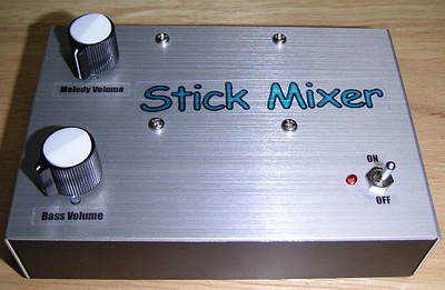
This device is a mixer that converts the stereo output of the Chapman Stick to mono. The bar has one stereo output, so you must use a dual-input amplifier or use two amplifiers. A two-input amplifier is expensive, and having two amplifiers is a hurdle. Using this device, you can use most commercially available mono-only amplifiers.
As a mixer for sticks, you can also use it as a mixer that can connect two guitars together by converting the stereo plug of the input to two mono plugs. It is also possible to connect four or eight guitars by changing the circuit.
You might think that even a commercially available mixer can be made mono, but there is a big problem. The output impedance of the passive receiver is about 566kΩ with the Fender single coil pickup pickup, as written on the Ishibashi Musical Instruments site. I don’t have any data on sticks, but sticks are annoying, so I think it’s about half that.
If you go to a musical instrument store you will find a variety of mixers, but most of them have an input impedance of around 10kΩ. Commercially available mixers are designed for connection from electronic devices and are not designed for high-impedance devices such as guitars.
Also, the output of passive receivers is very weak. Commercially available mixers have a circuit that synthesizes the signal without amplifying it. If it’s a strong signal like a normal electronic device, it’s fine, but if it’s a weak signal like a passive receiver, it will be greatly attenuated.
Therefore, if you use a commercially available mixer, the sound will be thin and the highs will be muddy. (I didn’t check as I don’t have a mixer.)
While searching for a product that can be used for commercially available sticks, I found a product called CUSTOM MIXER from CUSTOM AUDIO JAPAN. However, the list price is \75,000, which is not a price you can buy for practice.
Op amp mixer circuit

In this Stick Mixer, the bass and melody input from the stick is amplified twice by the first stage operational amplifier and mixed by the second stage operational amplifier. The 3rd stage returns the inverted signal in the 2nd stage mixer circuit to positive phase. If mixing is done with non-inverting amplification, the third step is not necessary, but Mr. Otsuka’s book says mixing should not be done with non-inverting amplification, so I use inverting amplification. I don’t understand why but I don’t think it’s a good idea because the 1-circuit op-amp will be dropped anyway.
The operational amplifier uses the TL072 for the first stage and the NJM5532 for the second and third stages. I chose this op amp by comparing the TL072, NJM4558, NJM4580, NJM5532 and NE5532. I used the TL072 because it looked the most like wires. If both are set to TL072, it will make a strange noise when power is turned off, so the second is the NJM5532. The sound is almost the same even if the NE5532 is used instead of the NJM5532. NJM5532 and NE5532 cannot be used for 1st stage as it is a high impedance input.
006P or 9V central negative AC-DC adapter can be used as power supply. However, since the no-load current is about 15mA, it can be used for a long time even with batteries. It might be better without the DC jack.
When using it for a guitar mixer, you can increase the number of guitars that can be connected by increasing the number of circuits from the input to R6.
The gain is set to about 2x, but if the sound isn’t sufficient with this setting, you can increase the volume by increasing the resistance of R10 and R21. The formula is (R10+R12)/R10=Gain. If you change R12 to 22k, it becomes (10k+22k)/10k=3.2 times (same for R21).
In addition, increasing the R7 value increases the gain. In this case, R7/R3 = gain. The gain of the entire circuit is the product of both, so change it so it’s not too big.
When I tried various values in the test, I felt that changing R10 and R21 had less effect on the tone.


TDA7318 Surround Sound System TDA8567Q Amplifier PIC16F628A Control
Normally only the hex code with source code projects that are not do not share, but this was an exception different project Surround Sound System, controlled, 2 × 16 LCD display (hue, temperature, etc..) For me which is remarkable supply SMPS both familiar circuit IR2151 and ATX powersupply made with transformer though I had previously shared a similar circuit IR2153 SMPS circuit made symmetrical with the only source of these circuits have 12v… .14v
IR2151 Switch mode power supply SMPS