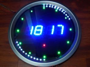
This project features a digital clock circuit with an alarm function and LED animations. The PCB design is quite good, and the LEDs around the display blink with various effects. The source code is PicBasic Pro, the Proteus simulation circuit, and the ARES PCB files are included. An alternative version using the PIC16F628 microcontroller is also available. It’s a great piece of work.
This project includes a digital clock circuit with an alarm function and LED animations. The PCB design is quite successful, and the LEDs positioned around the display work with different animation effects.
The PicBasic Pro source code, Proteus simulation circuit, and ARES PCB design files for the project are shared. An alternative version using the PIC16F628 microcontroller is also available. Overall, it’s a fantastic clock project both functionally and visually.
Project Features (@fhroz description)
Contents
The circuit includes functions such as clock, temperature (degrees), alarm, LED animations, and hourly alert sound (between 21:00 and 08:00).
The temperature value is displayed with 0.1 °C accuracy. The alarm is turned on and off using the UP button, while alarm settings are adjusted using the DOWN button. A melody plays when the alarm is active.
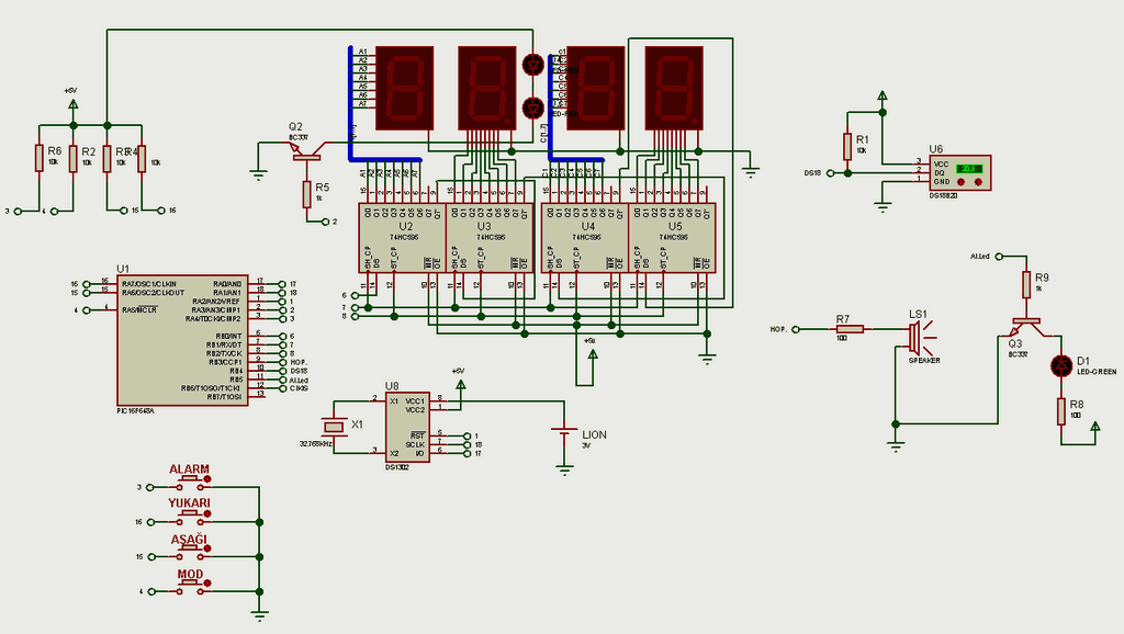
The PCB diameter is designed to be 25 cm, and an ARES PCB design suitable for these dimensions is available. Suitable enclosures for the circuit can be easily found in hardware stores or hobby shops. The displays used are 38 mm anode type. The PIC16F648A microcontroller is preferred.
Knowledge grows by sharing.
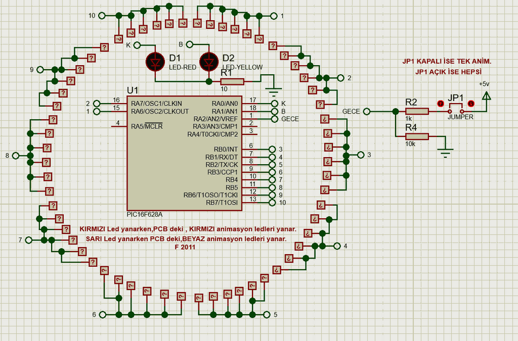
LED Animated Clock Circuit Diagrams
Key Functions and Menu Usage
Pressing the UP key while on the clock display activates or deactivates the alarm.
Pressing the ALARM button enters the alarm settings menu.
Using the UP/DOWN keys, you can set the alarm time.
Using the MODE key, you can set the alarm minutes.
Using the UP/DOWN keys, you can also set the alarm minutes.
Pressing the MODE key exits the alarm menu.
Using the DOWN key enters the date settings menu.
Settings are made using the UP/DOWN keys; the MODE key moves to the next step or exits the menu.
Additional Features
When the temperature rises below 21°C or above 29°C, a warning icon showing one degree per minute is displayed at the bottom of the displays (software controlled).
If the JP-1 is turned off while the LED animations are running, the system will switch to single animation mode (between 00-08) after all animations are completed.
PCB Specifications
1. PCB – Main Clock PCB (25cm outer diameter round clock – 38mm anode display.LYT)
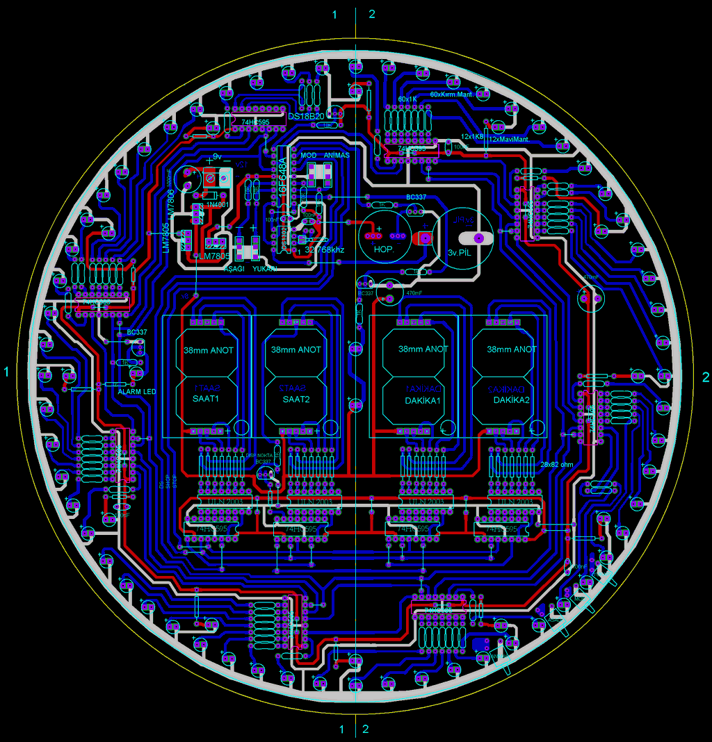
This PCB forms the main body of the clock. It has a round design with a diameter of 25 cm and is suitable for 38 mm anode type displays.
The 8 74HC595 shift register integrated circuits that drive the animation LEDs around the display are designed to be mounted on the copper (bottom) surface.
This arrangement reduces cable clutter and provides a cleaner PCB layout.
2. PCB – Two-Color LED and Animation PCB (2Renk-Led displey.LYT)
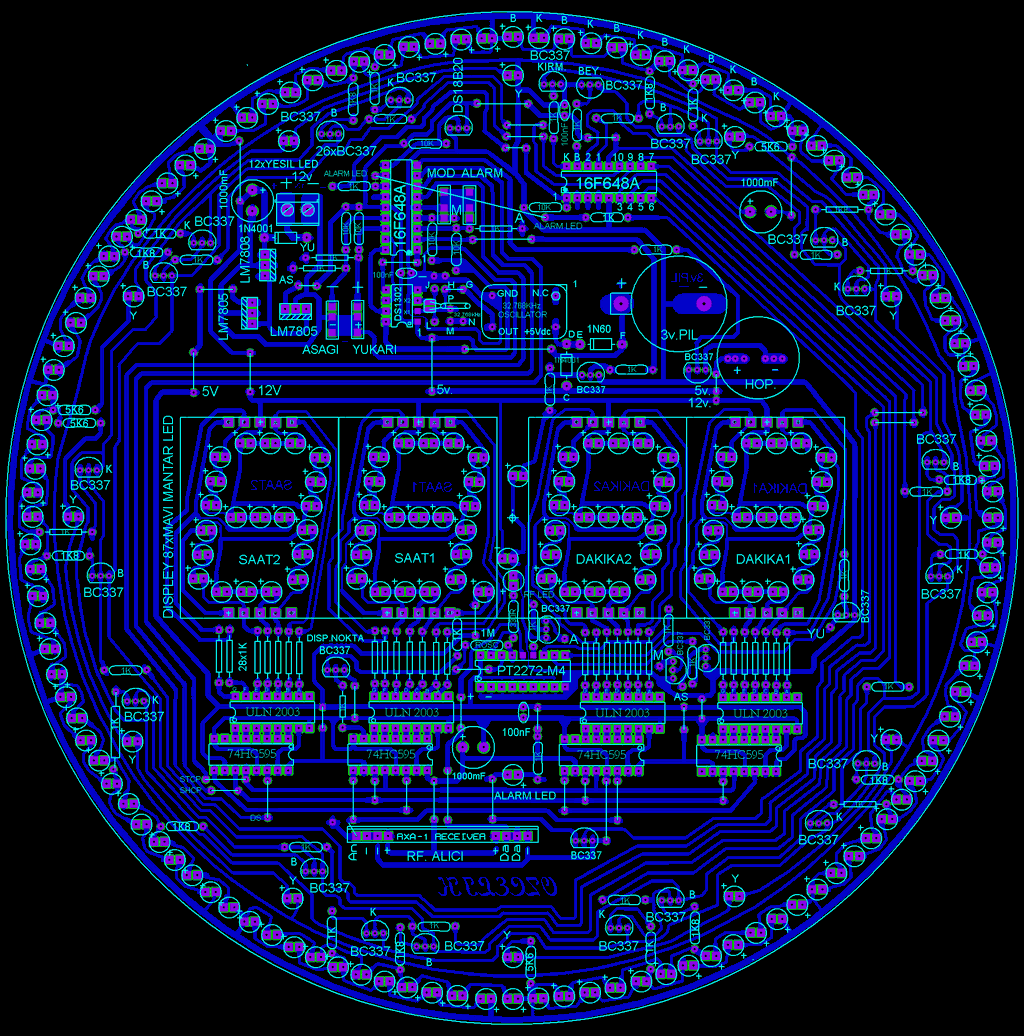
The LED distribution and colors used on this PCB are as follows:
87 display LEDs – Blue mushroom LEDs
12 hourly alert LEDs – Green mushroom LEDs
61 animation LEDs – Red mushroom LEDs
60 animation LEDs – White mushroom LEDs
Important: Animation LEDs must be installed paying attention to the positive (+) and negative (-) terminal directions during assembly.
Hardware and Component Information
If using an oscillator crystal, a cylindrical type 32.768 kHz crystal should absolutely not be installed.
Main integrated circuits and components used:
2 × PIC16F648A
DS1302 (RTC – real-time clock)
DS18B20 (temperature sensor)
4 × 74HC595
4 × ULN2003
26 × BC337
2 × LM7805
1 × LM7808
4 × 10 mm tactile buttons
32.768 kHz crystal
Resistors:
55 × 1K
10 × 1K8
4 × 5K6
5 × 10K
Capacitors:
3 × 100 nF
3 × 1000 µF
Diodes:
2 × 1N4001
1 × 1N60
Other:
3V battery holder
Speaker
2 × 18 Pin Socket
1 × 8 pin socket
RF Remote Control Support
RF Receiver Module:
PT2272-M4
18 pin socket
4 × BC337
330 Ω resistor
8 × 1K resistors
ROSC connections and LED
RF 4-Channel Transmitter: A ready-made module with PT2262 integrated circuit will be used. Pins 1–8 on the transmitter and receiver sides must be connected in exactly the same way.
On the PCB; M-M, A-A, YU-YU, AS-AS connections and RF receiver pin connections are pre-designed.


Note: The circuit has been tested with Proteus 8 and no issues were found. Since the project was created in an older Proteus version, if the “Saat_led disp.dsn” file does not open directly, the .dsn file must be imported using the File → Import Legacy Project menu.
Videos of LED Animated Clocks with Display
Prepared by @fhroz from the electrical science forums. Thanks to everyone involved in preparing this.


L297 IR2104 IRFZ44 High Power Bipolar Stepper Motor Driver Circuit
Power stage, in an integrated motor driver integrated with power limited is happening in this circuit L297 stepper motor controller integrated outputs of the ir2104 and strengthened irfz44 MOSFETs driven PCB layout regularly also in different shapes printed circuit drawing exists in the circuit pretty been popular members of their applications shared (+ proteus isis ares drawings sharing the There) test images with the Mach3 cNC controls have made.
لالللل