BMS 3S 25A modules are widely preferred, especially for Li-ion battery conversions in cordless drills. The most important advantages of these modules are their cell balancing, overcurrent, overcharge, overdischarge, and short-circuit protection.
Although they have a nominal current capacity of 25A, their ability to allow short-term current surges of 34–40A makes them attractive for high-power applications.
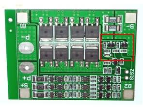
The small PCB size and on-board cooling of the MOSFETs are also significant advantages. However, for applications operating with continuously high currents, adding an external heatsink to the MOSFETs is recommended.

The Emergence of the BMS Protection Problem
Contents
In some cordless drill applications, it has been observed that the BMS 3S 25A module unexpectedly activates its protection under load. While this might initially appear to be overcurrent protection, the real reason is usually a sudden voltage drop under load. The internal resistance and overall health of the batteries are also determining factors in this process.
The author (@ksiman), who investigated this situation, shared the following technical findings:
Initially, I thought the module was activating due to overcurrent. Even after disabling the shunt resistor, the result remained the same. Then, I connected an oscilloscope in recording mode to the battery terminals and monitored the voltage while the motor was running. The protection activated the moment the total battery voltage dropped below 7V under load.
Measured and Calculated Values
Total battery voltage: 11.4 V (3S Li-ion)
Internal resistance of batteries: 66 mΩ (3 × 22 mΩ)
Measured motor resistance: 63 mΩ
Resistance of connecting wires and trigger switch: 23 mΩ
Protection circuit resistance (shunt + MOSFET + traces): 10 mΩ
Total circuit resistance: 66 + 63 + 23 + 10 = 162 mΩ
Theoretical current flowing through the circuit: 11.4 V / 0.162 Ω ≈ 70 A
The main problem here is not the high current, but the voltage drop per cell under load.
At 70A current, the voltage drop across each cell is: 70 × 0.022 Ω = 1.54 V.
The nominal 3.8 V cell voltage under load is: 3.8 − 1.54 = 2.26 V.
This value drops below the BMS’s over-discharge protection threshold, causing the module to immediately activate protection. This is the main trigger.
BMS Troubleshooting and Modification Applied
Completely removing or aggressively modifying the protection thresholds would severely reduce battery safety. Therefore, as a safer approach, the discharge protection delay time has been extended. This prevents the protection from activating during the high current draw at the initial start-up of the motor.
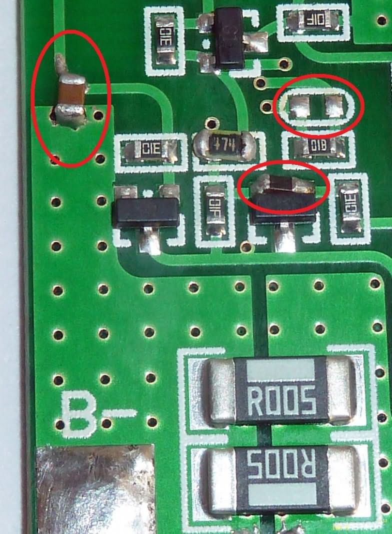
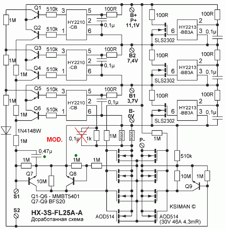
For this purpose, a 0.47 µF capacitor has been added to the circuit, increasing the discharge protection delay time from approximately 25 ms to 300 ms. If soldering is difficult, this capacitor can be surface-soldered between the S1 and B- terminals. Explanation of All Modifications
The 0.1 µF capacitor soldered to pin 2 of the HY2210 integrated circuit has been removed.
The reason for this capacitor’s presence in the circuit is unclear and it is not mentioned in the HY2210 datasheet. It was found to be unnecessary in practice.
To stabilize the post-protection auto-reset, a resistor has been added between the base and emitter of the relevant transistor.
Without the resistor, the protection reset after the load is disconnected operates unstably. Even the smallest interference on the P-line can prevent the reset.
Suitable resistor value: 1 MΩ – 3 MΩ
The resistor is soldered directly to the transistor legs. Care should be taken not to overheat the transistor during soldering.
A 0.47 µF capacitor has been added to increase the over-discharge protection delay.
After this modification, the drill operates smoothly without triggering the protection on initial startup.
BMS PCB Modifications
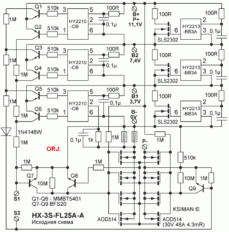
Original and Modified BMS 3S 25A Circuit Diagram

Note: 5A 70 degree thermal fuse is optional. If possible, it would be good to use it for protection and security.


how about bms 4s? have same problem
check your 4s board it might be similar
Great effort you have done and solved a common problem. first of all Thank you a lot for this effort. you have used 0.47uF capacitor to increase the over-discharge protection from 25ms to 300ms.
Now please suggest me if I want to decrease the over-discharge protection from 25ms to 1000ms which capacitor will used. Thanks again.