
Active crossover is an improved solution for loudspeakers compared to traditional passive crossover circuits. It provides excellent flat system frequency response and reduced distortion.
Phase-corrected active crossover: An active crossover circuit that reduces distortion, cost, critical components, and the effects of deviations in component values.
Crossover Designs
Contents
Passive Filtering:
Traditional high-quality loudspeaker systems typically included a 2- or 3-way passive crossover circuit to split the amplifier output signal according to the frequencies the drivers were designed for. Passive crossover circuits can be expensive and cause unwanted distortion.
Active Filtering:
Active crossover filters involve filtering signals at the line level and using a separate power amplifier for each driver.
Active crossover filters are more stable, produce less distortion, and are less expensive. However, they require separate power amplifiers for each driver unit.
In the past, this had significant cost implications, but as silicon costs continue to fall year after year, the argument against active crossover filters is becoming less significant each year.
Disadvantages of Traditional Design
Overall System Frequency Response: A traditional crossover filter design filters high, low, and mid frequencies separately.
This makes component tolerance and drift critical, as the matching of these components affects the overall system frequency response.
Critical Component Matching: The reliance of traditional pass filters on critically matched components creates a significant cost impact.
Since a passive pass filter affects the amplifier’s output signal, the components must possess high current, high voltage, high accuracy, and very high stability characteristics.
In short, while a poor but cheap pass filter can be manufactured, a good passive pass filter is generally quite expensive.
Damping Factor: Modern amplifiers can have impressive damping factors, but passive pass filters can degrade this at certain frequencies.
Around the pass frequency, the series components in passive pass filters render the amplifier damping factor practically negligible, with the series impedance increasing towards the pass frequency.
Due to poor driver monitoring, the result is increased distortion and oscillation at these critical frequencies.
Active Pass Circuit Design

The following active crossover circuit does not require high-voltage or high-current components because it operates at line level.
More importantly, the circuit achieves an excellent flat overall system frequency response even with components that are not high-tolerance or highly stable.
This is achieved by using a single filter circuit to filter only one of the outputs; the other output is generated as the difference between the input and filtered output signals.
This design offers a good damping factor thanks to its active nature and the direct connection between the power amplifier and the driver. This reduces distortion by ensuring optimum driver tracking.
The Active Crossover circuit can be operated with any power supply that provides a dual-line, symmetrical voltage (+5V to -5V and +15V to -15V).
Two-Driver Active Crossover Configuration

In the two-way design, only a high-pass filter is used; the low-pass filter is obtained as the difference between the input and high-pass output signals. Two NE5532 Opamps are used.
This automatically provides a system with a flat frequency response, eliminating the need for expensive and critically matched components.
Three-Driver Active Crossover Configuration

In a three-way design, two non-overlapping filters are used: one high-pass and one low-pass filter. Two NE5532 Opamps are used.
The band-pass mid-frequency range is obtained as the difference between the input and the sum of both the high-pass and low-pass output signals.
This automatically provides a system with an excellent flat frequency response, eliminating the need for expensive and critically matched components.
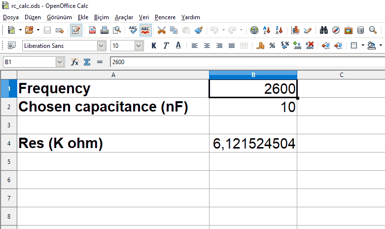
You can perform the filter calculation using the RC calculation spreadsheet (.ods format) prepared with the free Open Office program.
Active Crossover PCB Design

The author has prepared the PCB design as a double-layer design; the drawing files are available in PDF format.
Additionally, I copied the 2-way and 3-way active crossover PCB designs using Sprint Layout 6.
If you wish to order PCBs from manufacturing companies, the PCB Gerber files are available.
The PCB designs have been checked but not tested.
Source opend.co.za/hardware/activeXO/index.html


