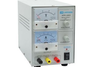
Following the older 0-30V 0-5A regulated power supplies, many XXX3005 model power supplies began to show a decline in quality. Through reverse engineering, the schematic of the LWDQGS APR-3005 power supply has been created and its operating system explained.
The device is of the linear type and contains two 2N3055 transistors mounted on a large heatsink at the rear.
There are three different voltage outputs for the mains supply. These outputs are selected via relays according to the required output voltage.
As the output voltage increases, it is possible to hear the clicking sound of the relays indicating that higher transformer windings are engaged.
This method aims to reduce unnecessary power loss and heat generation. There is also a separate AC output from the transformer to power the control electronics.
See: Relay bypass circuit for regulated power supplies.
0-30V 0-5A Adjustable Power Supply Circuit Diagram
Contents

The circuit diagram shows a transformer on the left with separate windings for power and control circuits. The upper section contains a series regulator consisting of two 2N3055 transistors.
The lower section contains the control circuit. This section can be divided into two main parts: the LM723 integrated circuit on the left provides voltage and current control, while the right contains two op-amps acting as comparators.
These op-amps drive two relays that select one of three different transformer windings depending on the required output voltage.
At very low output voltages, relay RL2 is active, and the lowest AC output is activated.
When the output voltage reaches approximately 10V, RL2 is deactivated, and the second transformer output is connected.
At approximately 20V, relay RL1 becomes active, and the highest transformer output is activated.
LM723 Current limiting circuit

The current-limiting transistor in the LM723 has a common emitter junction with the 2SC9014. When the current increases, the 0.18Ω resistor creates a voltage drop.
The current-limiting transistor conducts and cuts off the base current of the output transistor.
For adjustment, start Rtrim at its maximum value and slowly reduce it until the desired maximum current limit is reached.
LM723 Voltage Regulation

The Vpot voltage varies between 0 V and -5 V, and the circuit sets the Vee output to the product of the Vcursor’s -7700/50000 (-6.5), so the output range is between 0 and +32.5 V.
Note: In the circuit diagram presented in the new PCB sharing for the Laboratory Power Supply 0-30V 10A (Adjustable) K7200, the 18V regulated Opamp and LM723 were powered from the transformer’s power winding. The same method can be applied to this circuit; it would be a practical solution if your transformer does not have an additional winding for the integrated circuit power supply.


Source: kakopa.com/APR3005/schema.htm


