
The circuit effectively protects the sensitive tweeter within a speaker cabinet from overload. It was specifically designed to prevent damage to tweeters, particularly at high volume levels and under faulty operating conditions.
According to DIN standards, a tweeter should not handle more than 1% of the total power applied to it under nominal test conditions. For example, in a speaker system capable of withstanding 100 W of power, this value is approximately 1 W for the tweeter. Even if the tweeter is physically large and well-cooled, in practice it can only safely withstand a few watts of power.
Considering the spectral distribution of audio signals, dividing the frequency components into appropriate speakers (woofer, midrange, tweeter) and determining the appropriate power values for each is a long-standing and proven approach.
However, it should be noted that increasing the amplitude by 6 dB around 4 kHz doubles the power transferred to the tweeter. This necessitates a larger tweeter in systems using advanced equalizer and tone control circuits.
The most critical situation for tweeters is when the amplifier is overdriven and reaches saturation (clipping). Under these conditions, transformerless semiconductor power stages, in particular, produce signals close to square waves at their outputs. When the spectrum of square wave signals is examined, it is seen that the amplitude of the high-frequency components increases dramatically.
This increase occurs even if the original signal contains only low frequencies. This is because the square wave contains numerous high-frequency harmonics in addition to the fundamental frequency.
As a solution to this problem, a small electronic circuit is used that limits the signal amplitude at the tweeter terminals. Thanks to fast diodes and transistors, this circuit works effectively even at frequencies above 100 kHz and protects the tweeter from overload.
Structure and Operating Principle of the Tweeter Protection Circuit
Contents
As a first step, a 2.35 Ω series resistor is added to the tweeter inside the speaker cabinet. This resistor is obtained by connecting two 4.7 Ω / 1 W resistors in parallel. As a result of this application:
For a 4 Ω tweeter, the power is reduced by approximately 30%.
For an 8 Ω tweeter, the power is reduced by approximately 20%.
Since many Hi-Fi speaker designs already have series resistors in the tweeter region, these resistors can be reduced or readjusted accordingly. If there were no series resistors in the circuit beforehand, this method leads to a reduction in the tweeter level of approximately 2–3 dB. This reduction is negligible in most cases and can be compensated for with a small tweeter boost if necessary.
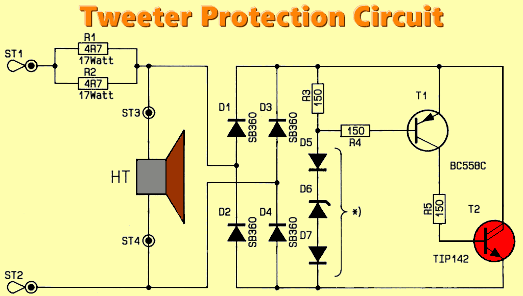
However, using only a series resistor does not provide true overload protection. At this point, the electronic limiter circuit shown on the right side of the circuit diagram comes into play. When the amplitude threshold defined by diodes D5–D7 is exceeded, transistors T1 and T2 conduct, effectively limiting the maximum amplitude at the tweeter terminals.
Tweeter Protection Circuit Diagram
Detailed Operation Description
The audio signal at the tweeter terminals is rectified by the D1–D4 SB360 fast diodes acting as a bridge rectifier and applied to the series structure consisting of the R3 150-OHM resistor and the D5–D7 reference diodes. At this point, when the reference voltage generated by the D5–D7 diodes exceeds approximately 0.6 V, current flows through R4 to the base of the T1 BC558C transistor.
When the T1 BC558C conducts, the Darlington power transistor T1P142 T2 is driven via the R5 150-OHM. T1P142 conducts, preventing the reference voltage from rising further, thus stabilizing the voltage generated through R3 and D5–D7.
As a result of this mechanism, the peaks of the AC signal on the tweeter are clipped from a predetermined voltage level. This provides highly effective overload protection for the tweeter.
To provide flexible use for different tweeter impedances and power levels, the reference voltage can be adjusted using up to three diodes. The table below shows how to select diodes D5–D7 according to the tweeter impedance and the maximum power at which limiting begins.
|
Ustart
Vss |
Umax
Vss |
Pstart (4-Ω)
W |
Pmax (4-Ω)
W |
Pstart (8-Ω)
W |
Pmax (8-Ω)
W |
DIODE
D5-6-7 |
|---|---|---|---|---|---|---|
| 3,4V | 5,6V | 0,36W | 1,0W | 0,18W | 0,49W | 1x1N4148 |
| 4,8V | 6,5V | 0,72W | 1,3W | 0,36W | 0,66W | 2x1N4148 |
| 6,2V | 7,8V | 1,2W | 1,9W | 0,60W | 0,95W | 3x1N4148 |
| 6,4V | 8,2V | 1,3W | 2,1W | 0,64W | 1,1W | 3,3V Z-Diode |
| 7,2V | 9,2V | 1,6W | 2,6W | 0,81W | 1,3W | 3,9V Z-Diode |
| 10,4V | 13,5V | 3,4W | 5,7W | 1,7W | 2,8W | 5,1 V Z-Diode |
| 13,6V | 16,0V | 5,8W | 8,0W | 2,9W | 4,0W | 6,2V Z-Diode |
| 18,0V | 20,0V | 10,lW | 12,SW | 5,lW | 6,3W | 8,2V Z-Diode |
Ustart: Peak-to-peak voltage measured just before the limiting circuit is activated.
Umax: Maximum peak-to-peak voltage reached under overdrive conditions.
Pstart (4 Ω): Power generated on a 4-ohm impedance tweeter at the point where the limiting circuit is about to begin.
Pmax (4 Ω): Maximum power allowed for a 4-ohm impedance tweeter.
Pstart (8 Ω): Power generated on an 8-ohm impedance tweeter just before the limiting circuit is activated.
Pmax (8 Ω): Maximum power value for an 8-ohm impedance tweeter.
Diodes: The diodes specified here must be soldered to the circuit. If fewer than two diodes or a single Zener diode are used, the empty diode locations must be short-circuited with a wire jumper.
Important Warning: If a standard 1N4148 diode is to be used instead of a Zener diode at position D6, the diode must be placed in the opposite direction to the symbol on the printed circuit board.
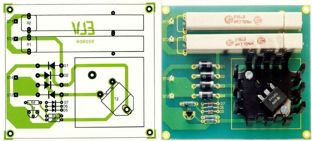
Circuit Assembly and Setup
First, determine the desired power level at which the protection should activate and select diodes D5, D6, and D7 accordingly.
Then, diodes D1–D4 are installed and soldered. After each soldering operation, the excess leads should be trimmed as short as possible.
Next, resistors R3–R5 and transistor T1 are mounted.
Next, the T2 T1P142 Darlington power transistor, with its middle leg cut off, is secured and soldered using M4 screws and nuts along with a finger-type heatsink.
In the final stage of assembly, the connection pins and high-power resistors are installed.
Testing and Commissioning
While testing the circuit, a power supply with a current limit of approximately 100 mA is connected to terminals ST1 and ST2, and the voltage is slowly increased starting from zero.
Simultaneously, the voltage across terminals ST3 and ST4 is measured. The limiting voltage is approximately UB/2, depending on the diodes D5–D7 used.
When the input voltage is reversed, the measured voltage must also be of the same magnitude but with reverse polarity. Speaker Cabinet Mounting
When placing the circuit in the speaker cabinet, sufficient heat dissipation must be ensured. The tweeter connection is disconnected, and the wires from the crossover are connected to terminals ST1 and ST2. The tweeter itself is connected to terminals ST3 and ST4.
To avoid phase error, the following point should be noted:
If the wire from the crossover, which was previously connected to one end of the tweeter, is now connected to ST2; the same end of the tweeter should be connected to ST4.
At low power levels, i.e., when limiting is not engaged, the circuit practically does not affect the audio signal. Therefore, this tweeter protection circuit can be safely used even in high-quality Hi-Fi speaker systems.
source: de.elv.com/p/tweeter-schutzschaltung-P202902/


