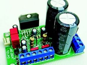
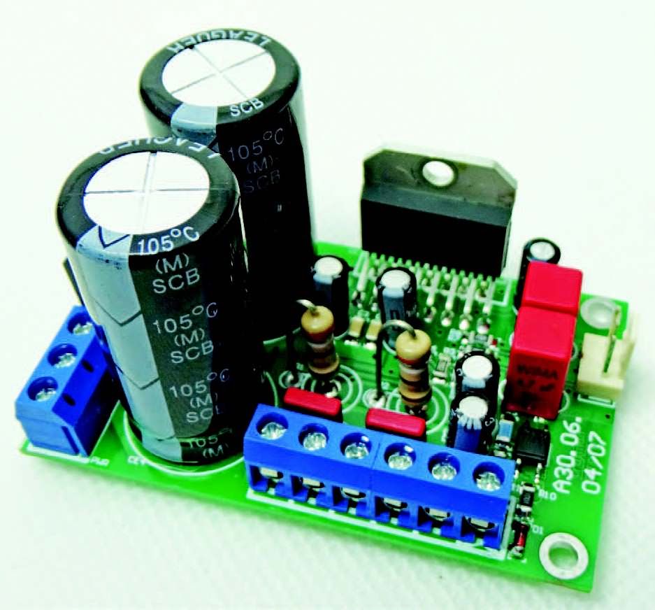
The module is based on the popular LM4766 chip, completed with a symmetrical power supply. The assembled plate is a ready-made functional block of the audio system. The circuit diagram is shown in circuit schematic. The U1 (LM4766) systems operate in a non-inverting configuration.
The input signal from the IN socket, through the C5 and C6 separating capacitors, is fed to the amplifier input. Resistors R3, R5, R4 and R6 close the feedback loop and set the amplification of the tip (sensitivity at 20W / 8OHM is about 1 Vrms). The RC (R1 / C1 and R2 / C2) circuits provide amplifier stability for inductive loads.
The system power supply is symmetrical and unstabilized, obtained from the BR1 KBL06 rectifier and the CE3, CE4 filter. The system, depending on the output power, is supplied from the 2×15 … 22 VAC 90VA transformer and the corresponding current efficiency.
The system is completed with an external muting circuit. Due to the reference to the negative pole of the VEE power supply, which is not very convenient for external control, the system has been supplemented with an IS optocoupler. Shorting the socket outlet ON, activates the amplifier.
LM4766 Amplifier Circuit Schematic
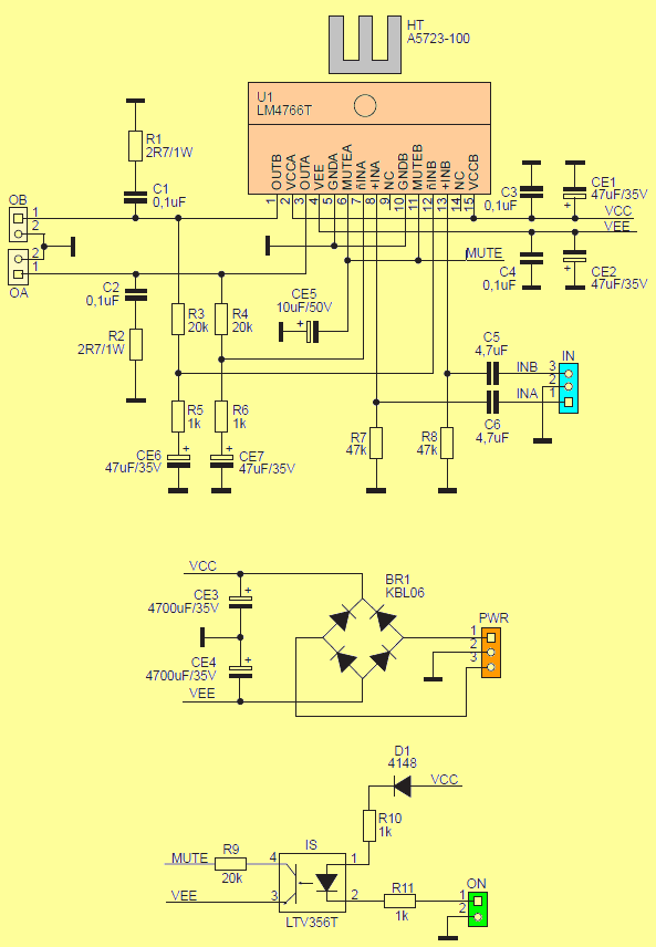
The system can be controlled by a relay or an OC type output, accepting a voltage of up to 35 V in the open state. If you do not need to mute the amplifier remotely, you can omit elements D1, R10, R11, IS, ON and short terminals 3-4 IS.
The amplifier was assembled on a double-sided PCB. The assembly is typical and does not require a description. Due to the power dissipated, U1 requires mounting on a heat sink with a suitable surface. Due to the connection of the radiator insert with the power supply, an insulating washer should be used and, of course, a thermally conductive paste. Of course, it is possible to use the insulated version LM4766TF and omit the insulation pad.
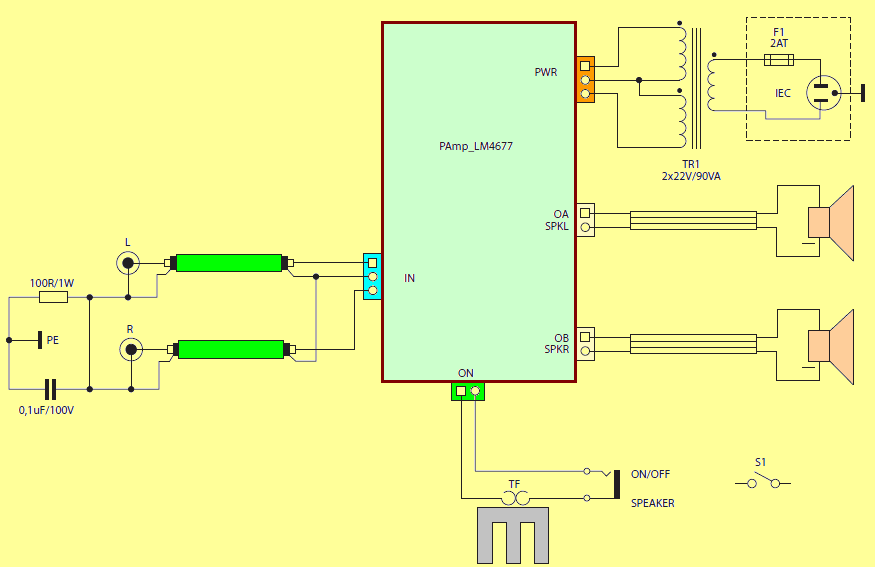
The method of switching on the amplifier. It is also possible to use the amplifier in the bridge version, for this purpose the signals of opposite phases should be led to the input, and the loudspeaker should be connected to pins 1, outputs OA, OB. This allows the amplifier to be used, for example, in the 2.1 system for powering the subwoofer and realizing the gain path on identical channel amplifiers.
LM4766 Amplifier Circuit casing connection
![]()
FILE DOWNLOAD LINK LIST (in TXT format): LINKS-26169.zip


Lead-Acid Battery Controller Circuit
Lead-Acid Battery Controller Circuit
The project deals with the solution of an electronic device for the control of lead Acid Battery. Lead-acid accumulators are susceptible to their excessive undercuts. The occurrence of these conditions in the lead-acid battery leads to a reduction in the life and capacity of the battery and, in the event of prolonged undercharging, the battery may become unusable. The main function of the controller is to monitor the voltage of the lead-acid accumulator and when it falls below the critical level (for 6-cell ie 12V Battery, the value of 10.5 V is normally considered) to disconnect the load from the accumulator. The second important feature the controller has is the possibility of charging the battery by connecting the AC adapter (with a voltage in the range of 16V to 26V). A ATTINY48 microcontroller can be advantageously used as the main control circuit, then other functions such as charging cycle counting, remaining battery indication, etc. can be considered.
The main control circuit of the entire device is the Attiny48 microcontroller from the AVR family of Atmel. This microcontroller has been selected because it has an integrated thermometer that can be used for rough ambient temperature measurements, and also has a PicoPower mode that takes just 100 pA. At the same time, it provides enough pins to connect external elements.
Block diagram power supply means the power connector for the AC adapter with DC output voltage between 16 and 26 V and input protection. The device is protected at the input from the network by a SMD fuse behind which there is a one-way transient diode, which protects the electronics against over-voltage input voltage and against excessive input voltage.
The Pb-battery charging block is a MC34063A step-down converter with adjustable output voltage and current limit (adjustable by potentiometers). The possibility of realizing a switched power source controlled directly by a microcontroller was considered, but this option was eventually dropped due to safety. The output voltage of the switched power supply is enabled and set by the signals of the microcontroller, which at the same time obtains information about the output current limitation from the switched source. Setting the output voltage by a microcontroller is understood only to decrease the output voltage by 0.5 V against the set value by a potentiometer for special cases (eg higher ambient temperature, etc.).
Module de circuit d’amplificateur LM4766
Le module est basé sur la puce LM4766 populaire, complétée par une alimentation symétrique. La plaque assemblée est un bloc fonctionnel prêt à l’emploi du système audio. Le schéma de circuit est illustré dans le schéma de circuit. Les systèmes U1 (LM4766) fonctionnent dans une configuration non inverseuse.
Le signal d’entrée de la prise IN, via les condensateurs de séparation C5 et C6, est envoyé à l’entrée de l’amplificateur. Les résistances R3, R5, R4 et R6 ferment la boucle de rétroaction et définissent l’amplification de la pointe (la sensibilité à 20W / 8OHM est d’environ 1 Vrms). Les circuits RC (R1 / C1 et R2 / C2) assurent la stabilité de l’amplificateur pour les charges inductives.
L’alimentation du système est symétrique et non stabilisée, obtenue à partir du redresseur BR1 KBL06 et du filtre CE3, CE4. Le système, en fonction de la puissance de sortie, est alimenté par le transformateur 2 × 15… 22 VAC 90VA et l’efficacité de courant correspondante.