The project deals with the solution of an electronic device for the control of lead Acid Battery. Lead-acid accumulators are susceptible to their excessive undercuts. The occurrence of these conditions in the lead-acid battery leads to a reduction in the life and capacity of the battery and, in the event of prolonged undercharging, the battery may become unusable. The main function of the controller is to monitor the voltage of the lead-acid accumulator and when it falls below the critical level (for 6-cell ie 12V Battery, the value of 10.5 V is normally considered) to disconnect the load from the accumulator. The second important feature the controller has is the possibility of charging the battery by connecting the AC adapter (with a voltage in the range of 16V to 26V). A ATTINY48 microcontroller can be advantageously used as the main control circuit, then other functions such as charging cycle counting, remaining battery indication, etc. can be considered.
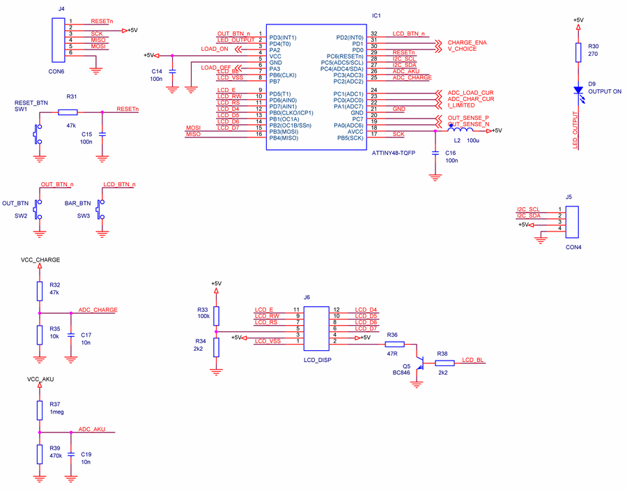
The main control circuit of the entire device is the Attiny48 microcontroller from the AVR family of Atmel. This microcontroller has been selected because it has an integrated thermometer that can be used for rough ambient temperature measurements, and also has a PicoPower mode that takes just 100 pA. At the same time, it provides enough pins to connect external elements.
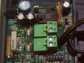
Block diagram power supply means the power connector for the AC adapter with DC output voltage between 16 and 26 V and input protection. The device is protected at the input from the network by a SMD fuse behind which there is a one-way transient diode, which protects the electronics against over-voltage input voltage and against excessive input voltage.
The Pb-battery charging block is a MC34063A step-down converter with adjustable output voltage and current limit (adjustable by potentiometers). The possibility of realizing a switched power source controlled directly by a microcontroller was considered, but this option was eventually dropped due to safety. The output voltage of the switched power supply is enabled and set by the signals of the microcontroller, which at the same time obtains information about the output current limitation from the switched source. Setting the output voltage by a microcontroller is understood only to decrease the output voltage by 0.5 V against the set value by a potentiometer for special cases (eg higher ambient temperature, etc.).
Lead-Acid Battery Controller Schematics
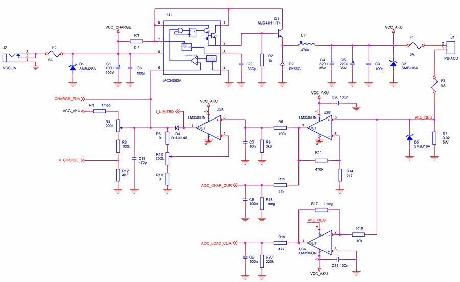
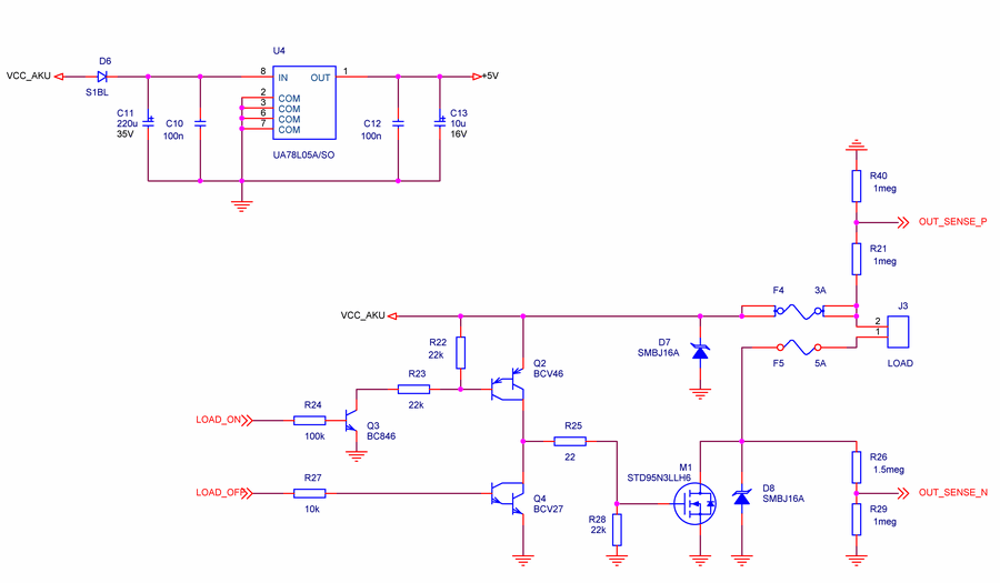
The Pb-accumulator and the devices are again protected by overcurrent fuses and unidirectional transil diodes. The microcontroller can detect the battery voltage and current (size and direction) through the A / D converter. From the battery voltage, the entire device is powered via a linear 5V stabilizer, shown by the system power block.
The load is connected to the accumulator via a low-loss STD95N3LLH6 MOSFET type N (the load is permanently connected to the positive terminal of the battery and is grounded by a transistor). The load management includes transistor protection elements, a fast fuse (classic tubular – for easy replacement) against excessive currents. It was considered to use a renewable fuse (so-called polyswitch) instead of tubular, but because of the long reaction time of a renewable fuse, a fuse had to be used – a renewable fuse would react only after all SMD fuses and that is certainly not appropriate. Again, both load poles are protected against unauthorized diode voltage transients.
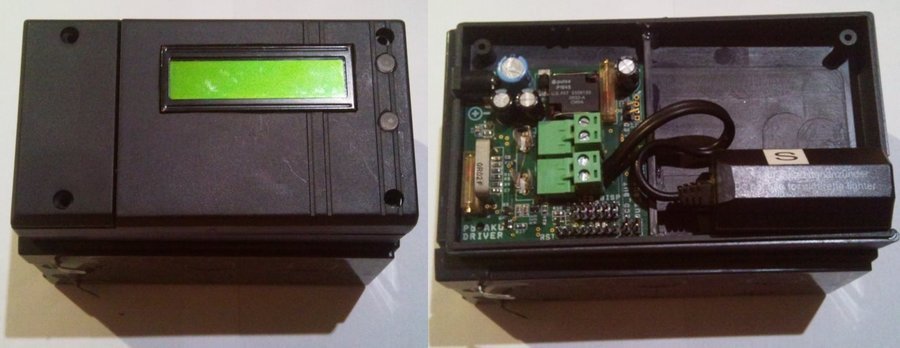
The user input is implemented by two buttons, one additional button is used to reset the processor in case of unexpected behavior. One of the buttons is used to turn on the display, which is only active when the user wants to view it to save battery power. The LCD shows battery voltage information and all other user information. The second button then turns the load on and off. This button is illuminated by an LED to indicate that the load is on. Again, to conserve battery power, the LED does not light continuously, but it is switched with a small rotation (approximately 100 ms on and 2 seconds off).
A simplified flowchart of the main loop program Firmware MCU
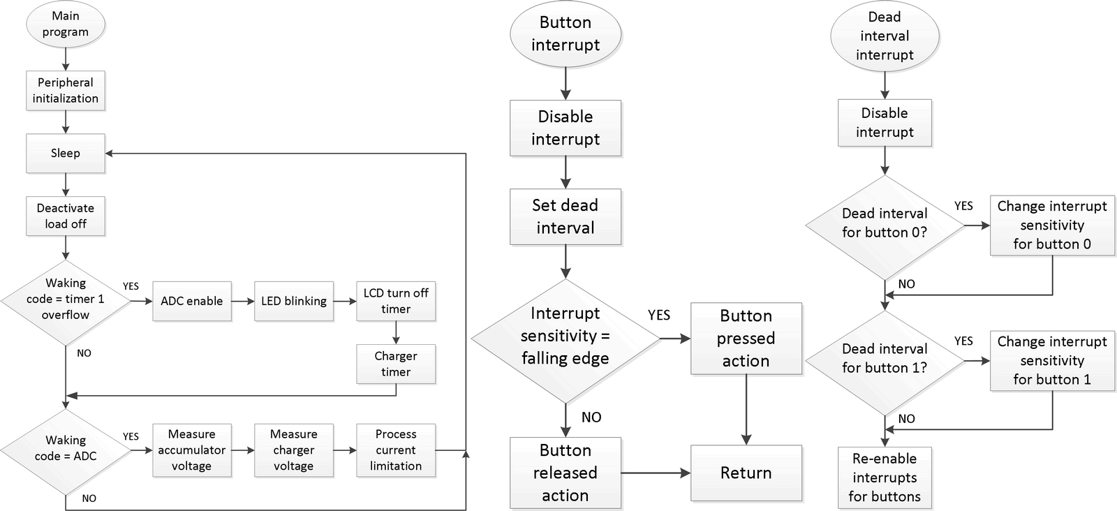
After the processor is started, all peripherals are initialized, the TIMER 1 timer is set for counting the time in the standard 8-point divider mode (the overflow interrupts at approximately 1.9 Hz) and the input and output pins are set.
At the beginning of the main loop, the processor goes to sleep. Wake-up is always an interruption event. If the timer is awakened by the timer 1 event that occurs approximately twice per second, the A/D converter is enabled and its multiplexer is set to sense battery voltage. In this wake-up event, the LED on the output is still on (when the output is on), after the preset time has elapsed, the display is turned off and the battery charging time is calculated by constant voltage. After 1 hour of constant voltage charging, the charger switches off – the lead-acid battery should not be permanently charged. After suspending the processor, the A/D conversion starts automatically.
If the processor has been awakened by the interruption of the A/D conversion, a state machine that switches the multiplexer to measure battery voltage first, then the input voltage of the charging circuit, and if charging is enabled, is also determined to determine whether the output current is limited. In the event that the charger output current is no longer limited, the above-mentioned constant voltage charging hour begins to count down.
Two user buttons are connected to external interrupt pins. One of the buttons turns the display on and the other button turns the load on and off. The process of servicing the external interrupt
When pressing a button, it is necessary to treat the glitches that arise on the button. Therefore, the interruption of the respective button is first disabled and the so-called dead interval is set in which the button does not respond. This interval is accomplished by interrupting timer 1 by matching the OCR1A register. OCR1A compliance interruption is shown in Fig. 4. The external interruption susceptibility changes at the end of the dead interval. The sensitivity evaluates whether the button was pressed in the external interrupt handler; or released.
The action to press the first button is to change the state of the load (from the on state it goes to the off state and vice versa). Pressing the second button responds by turning on the display for a defined period of time (currently set to about 4 s).
You can measure the remaining battery power at least two ways. One way is to determine the speed at which the battery voltage decreases depending on the discharge current after the load is connected. From these two values, the directions of the discharge curve are determined and, according to the calculated directive, they then try to estimate the remaining battery capacity. This measurement is mainly used when a completely unknown battery condition is available. However, in the device, information about battery charging and monitoring of the entire discharge process can be advantageously used (if we neglect slow self-discharge). Then, the remaining battery power (assuming full previous charge) can be calculated as the difference in battery capacity and discharge current integral time. The calculation is simplified because the capacity of the accumulator is given for a defined constant current equal to 0.05 C. For a larger current, the capacity of the accumulator is smaller and, for the smaller one, larger. To calculate precisely, it would be necessary to take into account the loss of battery capacity with its lifetime. This parameter could be derived from previous charging and discharging characteristics. Both methods can be combined to achieve more accurate measurement of the remaining battery power.
The device works as required. However, measuring the remaining battery power has not yet been implemented in the program, it will be completed as soon as possible in the form described above. In the course of the implementation several facts were found which were not taken into account in the proposal. The original 5V stabilizer 78L05 was originally designed, but the problem with this stabilizer is that its own power consumption is 5mA, and that is too much for a battery powered application. Fortunately, this stabilizer can be replaced with a pin compatible, which has a power consumption of less than 50µA. Furthermore, it was necessary to add operational amplifiers over the design range to switch their power supply to the processor because their quiescence is 2mA, and since the processor only needs to know the current once every 0.5 seconds, it is unnecessary to power them all the time.
It was found in programming that it would be more appropriate to use an Atmega-type processor for a similar project because of the ability to step through the processor via JTAG, which would save a lot of debugging time. The cost of such a processor would be quite acceptable for a single piece of equipment, and the processor would provide much more resources. In the case of more stringent consumption requirements, it would be necessary to use processor power with a lower voltage (ideally 1.8V), but then it would be necessary to solve the level translation for some peripherals (eg LCD).
FILE DOWNLOAD LINK LIST (in TXT format): LINKS-26157.zip


LM4766 Amplifier Circuit Module
LM4766 Amplifier Circuit Module
The module is based on the popular LM4766 chip, completed with a symmetrical power supply. The assembled plate is a ready-made functional block of the audio system. The circuit diagram is shown in circuit schematic. The U1 (LM4766) systems operate in a non-inverting configuration.
The input signal from the IN socket, through the C5 and C6 separating capacitors, is fed to the amplifier input. Resistors R3, R5, R4 and R6 close the feedback loop and set the amplification of the tip (sensitivity at 20W / 8OHM is about 1 Vrms). The RC (R1 / C1 and R2 / C2) circuits provide amplifier stability for inductive loads.
The system power supply is symmetrical and unstabilized, obtained from the BR1 KBL06 rectifier and the CE3, CE4 filter. The system, depending on the output power, is supplied from the 2×15 … 22 VAC 90VA transformer and the corresponding current efficiency.
The system is completed with an external muting circuit. Due to the reference to the negative pole of the VEE power supply, which is not very convenient for external control, the system has been supplemented with an IS optocoupler. Shorting the socket outlet ON, activates the amplifier.
Circuit de contrôleur de batterie plomb-acide
Le projet porte sur la solution d’un appareil électronique pour le contrôle de la batterie au plomb. Les accumulateurs au plomb sont sensibles à leurs contre-dépouilles excessives. La survenue de ces conditions dans la batterie plomb-acide entraîne une réduction de la durée de vie et de la capacité de la batterie et, en cas de sous-charge prolongée, la batterie peut devenir inutilisable. La fonction principale du contrôleur est de surveiller la tension de l’accumulateur au plomb et lorsqu’elle tombe en dessous du niveau critique (pour une batterie à 6 cellules, c’est-à-dire 12V, la valeur de 10,5 V est normalement prise en compte) pour déconnecter la charge de l’accumulateur . La deuxième caractéristique importante du contrôleur est la possibilité de charger la batterie en connectant l’adaptateur secteur (avec une tension comprise entre 16 V et 26 V). Un microcontrôleur ATTINY48 peut être avantageusement utilisé comme circuit de commande principal, puis d’autres fonctions telles que le comptage de cycles de charge, l’indication de batterie restante, etc. peuvent être envisagées.
Hello,
I need current sense circuit only,
May I know the current circuit exactly in this design.
Please let me know as soon as possible.
Thank you,
With regards,
Hello,
Current sensing by measuring R7 resistance