LM3886 has long been a popular power amplifier IC in hobby and semi-professional audio projects. The main reason for this is that it can provide high sound quality with relatively few external components and includes important protections such as temperature, short circuit, and overcurrent protection.
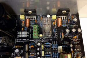
In this project, the classic LM3886 applications have been taken a little further, and the pre-stage, DC servo, speaker protection, and auxiliary power supply have been combined in the same structure. The result is a design collected on a single board, directly applicable, and capable of satisfying users who have serious expectations on the audio side.
The first version is here: LM3886TF Stereo Speaker-Protected Amplifier Circuit NE5532 DC Servo

The notable side of the circuit is that it is designed to operate without being forced to use a coupling capacitor in the signal path. This is ideal especially for users who want to reduce unnecessary series capacitors from input to output.
Of course, at this point, DC offset control and speaker safety become much more important. Therefore, both the DC servo and the relay-based speaker protection section are used together in the schematic.
How do the circuit blocks work?
Contents
- 1 How do the circuit blocks work?
- 2 Preamplifier: the section that prepares the input signal cleanly and in a controlled way
- 3 LM3886TF output stage: the main power section of the project
- 4 What does the DC servo section do?
- 5 The importance of the speaker protection circuit
- 6 Power supply side: in this project, half of the success is the power supply
- 7 Things to pay attention to in component selection and assembly
- 8 Outstanding advantages of the LM3886TF amplifier

The schematic consists of four main sections: op-amp based pre-stage, LM3886 output stage, DC servo section, and speaker protection circuit. The power supply section is also considered separately for stable operation of these structures.
Preamplifier: the section that prepares the input signal cleanly and in a controlled way
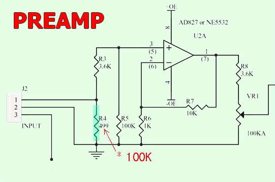
On the left side of the schematic, there is the pre-stage section shown as U2A.
Here, the use of a dual op-amp such as NE5532 or AD827 is intended. The input signal is first processed in this section, and level adjustment is made with VR1.
This is useful in terms of providing a more controlled input level instead of driving the LM3886 directly.
For the pre-stage, NE5532 is a practical and easily available choice. For those who want to try different op-amps, a socketed setup makes sense.
This method is already very useful for those who want to experiment with op-amp character in audio circuits.
However, the important point here is not to expect that “everything will change miraculously when the op-amp is changed.” First, proper power supply, correct grounding, and good layout are required.
A note has been added on the schematic for R4, one of the values used on the pre-stage side, saying that “it is recommended to make it 100K.”
Such notes are usually added according to input impedance, offset behavior, or stability results obtained in practice.
For those who will build the board exactly, it would be appropriate to take this note into account.
LM3886TF output stage: the main power section of the project
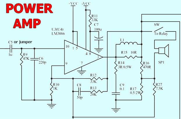
U3 located in the center is the LM3886 power amplifier IC. Although the circuit looks close to the classic datasheet application, it has been made more stable with some arrangements around the feedback and surrounding parts.
The network around L1, R15, and R16 is important for output stability. Especially when the speaker cable is long or the load shows a reactive character, this type of Zobel and output coil combination helps prevent the amplifier from going into oscillation.
In applications made with LM3886, focusing only on output power would be a mistake. The same IC can operate with a noisy and harsh character with poor PCB layout or a weak power supply.
On the other hand, with a good transformer, sufficient filtering, and short current paths, it gives extremely satisfying results. Therefore, in the project, the power supply and grounding should be taken as seriously as the power stage.
For those who want to compare similar IC-based solutions, the LM3886 stereo complete amplifier project may be useful, and for those who want to look at different topologies, the integrated audio amplifier archive may also be helpful.
What does the DC servo section do?
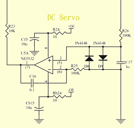
The DC servo circuit built with U5A NE5532 in the lower section monitors the direct current component at the output and tries to keep it close to zero with slow feedback.
Thanks to this servo approach, which operates in the very low-frequency region without affecting the audio band, small offsets in the input or gain chain are not carried to the speaker as DC.
The network surrounded by C15, C16, C17, and diodes in the schematic also determines the response character of the servo.
This section is not a fast tone-shaping stage, but a slow operating balancing mechanism. In other words, its purpose is not to change the sound, but to keep the output center point under control.
The most practical result of this structure is that the C5 capacitor at the input can be removed if desired. However, caution is required here.
If the board is not made with clean grounding, if the op-amp offset is high, or if there is an assembly error, completely removing the coupling capacitor may create risk.
Starting the first test with C5 and evaluating the bridging option later if the measurements are healthy is a safer method.
The importance of the speaker protection circuit
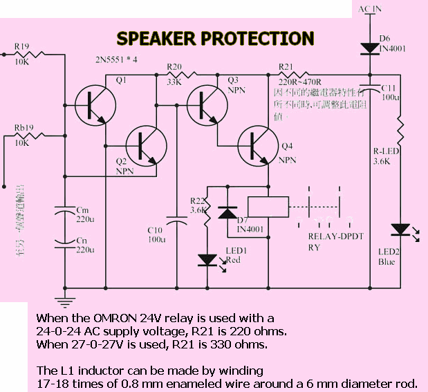
The relay-based protection section on the right side is a part that should not be neglected, especially in DC-coupled amplifiers. The structure built around Q1, Q2, Q3, and Q4 monitors the output line; when abnormal DC occurs, it releases the relay and disconnects the speaker. In addition, providing a short delay at startup reduces the risk of a “pop” sound.
Although LM3886 has some internal protections, a separate relay-based system is much more reassuring for protecting the speaker directly against DC.
Especially during the testing phase, when using different op-amps, or during the first energizing of a newly built board, this stage provides a great advantage.
If you want to see separate examples specific to this subject, the speaker protection circuit against DC voltage at the amplifier output is also a good complementary content.
Power supply side: in this project, half of the success is the power supply

In the lower schematic, the bridge rectifier, large filter capacitors, and auxiliary regulator stages are seen.
The main power section produces a symmetrical supply through a center-tapped transformer.
For the auxiliary op-amp stages, a ±15 V regulated line is obtained with 7815 and 7915.
In this way, the pre-stage and DC servo section are less affected by power supply fluctuations that may be caused by the LM3886 output current.
| Section | Recommended structure |
|---|---|
| Main transformer | In the range of AC 22-0-22 V to 28-0-28 V, preferably above 3 A or approximately 200 W and above |
| Main rectification | Bridge diode + large filter capacitors |
| Pre-stage / servo supply | ±15 V symmetrical regulated with 7815 and 7915 |
| Grounding | Thick current paths should be kept short, signal and power returns should not be routed randomly |
One of the most common mistakes in audio circuits is combining a good amplifier schematic with a poor power supply.
If the transformer is selected weakly, bass sag, harshness at high volume, and hum problems occur.
If you want to strengthen the calculation side in this section, the amplifier power supply calculations article will also help with the practical side of the work.
Things to pay attention to in component selection and assembly
- A heatsink is required for LM3886TF. Although the TF package is insulated, operating it with a small heatsink is not correct. Thermal paste should be used for heat transfer.
- Do not leave the power paths thin. If the board will be made at home, the copper paths carrying high current can be thickened with solder.
- Maintain the star ground logic. Especially carrying the input ground and speaker return current on the same thin line creates hum.
- Perform the first power-up with a series lamp or current-limited supply. Instead of connecting the speaker directly, first measure the output DC offset.
- Use the op-amp with a socket. Maintenance becomes easier, and it also provides an advantage for those who want to experiment.
Outstanding advantages of the LM3886TF amplifier
The main point that distinguishes this circuit from an ordinary LM3886 application is that it is designed as a system, beyond being just “a working amplifier.”
Handling the pre-stage separately, adding a DC servo, not forgetting speaker protection, and regulating the auxiliary power supply make a difference in real use.
Especially the single-board structure reduces wiring errors.
A significant part of failures in high-power audio circuits made at hobby level are caused by incorrect cable routing, long ground returns, and loose connections.
This type of integrated solution makes assembly a little denser, but ultimately provides a more organized application.
In summary, we are looking at a design that preserves the practicality of the LM3886 while making the audio chain more mature.
When DC servo and speaker protection are considered together, both the sound quality and safety side become stronger.
With the correct transformer, clean assembly, and careful initial tests, this circuit can easily be used as a high-quality home-type mono power amplifier.
Note: When selecting the series resistor according to the relay coil voltage in the schematic, the actual no-load output voltage of the transformer to be used must definitely be measured.
Source: gc.digitw.com/new_page_12.htm


