Nokia 3310 screen already had several applications with bi-color LCD at this time I decided to experiment with it. Heavily on the market, the Nokia 6100 LCDs and their controllers for microchip using Atmel ATmega8 given codes can edit and work with Winavi made to optimize and tried with ATmega8 code works just fine.
220Ω, and 330Ω with ATmega8 voltage divider screen I used to drive. But who wants to run ATMega8 3.3 volts without the use of resistance can take the screen. Including 8-bit and 12-bit color display mode has two 8bit color I did with trials. Drivers in the file by writing to the screen, draw various geometric shapes and functions available in press bmp image. All the files associated with the application can be accessed from the link below.
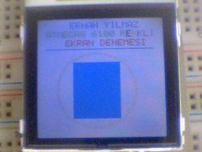
Atmega8 PCF8833 Nokia 6100 project


Atmega-8 Nokia 6100 lcd pcf-8833 application source code and the circuit diagram:


Tank Robot ATMEGA48 Bluetooth java Project
Atmel ATMEGA48 made with an advanced robot. Control program bluetooth control, and have the java program the robot tank in the engine control L293 bridge driver is provided with source code included hunting eagle printed circuit prepared with the schema files..
ATMEGA48 Robot Bluetooth Project