The keyboard on the computer recording the transactions in the know Keyloger programs between two PC’s with this circuit you can do the same process as wireless
Coding in C language prepared by a different project or my işetişi wireless data radio frequency control on the computer can be useful for people interested in Receiver Circuit is added to the cable connecting the keyboard to the computer via the keyboard atmega8-P sadder entered into before the circuit board to the computer is going through and transmitter circuits

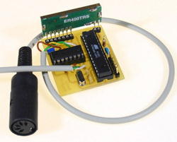
The actual Keylogger is relatively simple. First, the data lines of the keyboard must be tapped. The occupancy of a DIN or PS / 2 connector is simple and consists of only one data line, clock, earth and +5 V. However, it was found that the lines are open collector and otherwise very sensitive to additional circuitry, so that it not without additional hardware is possible to tap off the signals.
The microcontroller will only analyze the data and not rich. As a useful component, the set 74HCT4053 out: This may the data lines “tap” and even interrupt. The keyboard is connected directly to mu.C and 4053 and the PC to the output of the 4053rd The circuit is supplied via the keyboard interface with voltage.
In addition, an ATmega8 microcontroller is still built in Minimum wiring and connected the radio module. Via the ISP interface , the processor can be programmed.

source blafusel.de Keyboard Spy Circuit with Atmel Atmega8 source code schematic alternative link:


2X50W Full Stereo Amplifier Circuit with TDA1514
Tone control is a nice application that consists of 3 parts, vu-meters, two-channel amplifier and two from the Input Selector integrated circuit TDA1514 used in integrated information 50w max output power
Amplifier can be connected to two devices at the CH1 and CH2 input signal can be selected with the button that selects the circuit CD4066 channel (Quad Bilateral Switch) and CD4011 (Quad 2-Input NOR Gate NAND Buffered) based on
TDA1524 Stereo tone control circuit bass treble balance in audio controls can be made based on the most beautiful 🙂 Loudness control circuit in addition to working with mono potentiometer’s bass sounds at low volumes is power