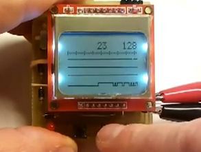
Built on the atmega 8 microcontroller Logic Analyzer circuit for nokia 5110 display lcd display kullanılanılıyor crafted with AVRstudio Software four. source software insurance settings schema, pcb, etc. files.
Frequency capture 400 kHz, Max input voltage 5v dc, operating voltage 5v (4 x 1.2 v rechargeable battery) to capture high speed signals, signal 3.7 ms, low-speed signals 36s
Note: If you are going to be the battery voltage of 1.2 v power supply for battery 1.5 v alkaline batteries if you use in total 6v voltage and atmega8.


Source: serasidis.gr/circuits/mini_logic_analyzer/miniLogicAnalyzer.htm
FILE DOWNLOAD LINK LIST (in TXT format): LINKS-18713.zip


Microcontroller Controlled VU Meter Circuit
KA2281 integrated circuits, LM3914, etc. According to the vu meter circuits with this circuit has been built on microcontroller circuit pic16f88 stereo really super 2×16 total 32 or mono 16 led, 40 can be used in the form of a burning LEDs the led dot bar looks very nice, but very complicated in different functions have led links the author has prepared a simple printed circuit board with a practical method vu meter circuit eagle schema, pcb drawings and follow the video source, you will see the hex codes for the given test asm, to-do list.