Transistor very useful for testing the circuit, but I do not know more pic programming with atmel series in seeing this type of advanced applications get confused 🙂
Transistor test circuit, BJT, MOSFET, triac, thyristor, JFET transistors and diodes can be measured. Source software and diagrams drawn with eagle pcb files there.
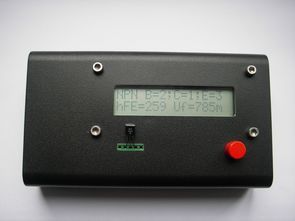
ATMega8 Transistor Tester

When the microcontroller ATmega8 has been selected. He has more than enough flash and RAM. He also has enough port pins and is very reasonably priced. The transistor tester is powered by a 9V battery. The 5V operating voltage for the AVR is quite conventionally generated with a 78L05. On port B of the ATMega8 various resistors are connected: the transistor pin a large (470 k) and a small (680Ω). Hereby two different currents can be applied to the test pin. The resistors are connected to ADC0, ADC1 and ADC2. At these pins and the transistor under test is connected. The left part of the circuit (with the 3 transistors) is responsible for the automatic shutdown. More on that later. On the first pins of port D, the LCD is connected. This is a 2×16 character text LCD with HD44780 compatible controller.
It should be noted that the test inputs do not have a protective circuit. A suppressor would probably distort the measurement results. It should therefore not be components that are still installed in a circuit under test. Otherwise, the ATMega8 could be damaged.

Transistor Tester Circuit Features
Automatic recognition of the NPN and PNP transistors, N-and P-channel MOSFETs, diodes (including double-diode), thyristors, triacs and resistors and capacitors.
Automatic calculation and display of the pins of the component to be tested
Detection and display of the protective diodes for transistors and MOSFETs
Determining the gain and the base-emitter forward voltage at transistors
Measurement of the gate threshold voltage and gate capacitance of the MOSFET
Display the values on a text LCD (2 * 16 characters)
Duration of a component testing: Less than 2 seconds (Exception: larger capacitors)
One-button operation; automatic shutdown
Power consumption in off mode: <20 nA
Source: http://www.mikrocontroller.net/ Transistor Tester Circuit files alternative link:


STM8-bit BCD Cycle Delay and 1 Wire Library
STM8 delay implementation of delay_us and delay_ms in Cosmic-C inline assembly. All delay done using inline macro _delay. Register X used as cycle counter, number of cycles per microsecond calculated by US and MS macros (decrement/branch lasts 3 CPU ticks). Millisecond delays made by delay_ms function. STM8 1wire library Library intended for communication with 1-wire devices. delay routines. To use it define (or edit ds1w.h) in/out port and bit macros DS1W_IN_PORT, DS1W_OUT_PORT, DS1W_BIT. STM8 bin to BCD conversions Useful for number indication. There are 8bit, 16bit, and 32bit conversions (Cosmic inline-asm). 8bit and 16bit conversions use hardware division, 32bit conversion done by shifts and BCD correction.