The main purpose of the circuit is to control the gate of the house. This DC motor and provided with two limit switches is provided by mechanical parts. The two buttons open and close the circuit inside is available. Sent to the ends of the drive motor integrated into 1 and 0 knowledge engine is turning left or right.
AT89C51RD2 switches are connected in series to the output port. As soon as the door closed one of the key information by sending port is disconnected. When the other button is pressed, this time the information is sent to one of the other ports and the engine returns to the other side and this time it is connected to the switch port opens.
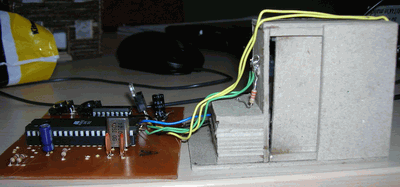
L293D DC Motor Door Control
Contents


L293D DC Motor Door Control Schematic PCB


L293D PIN connecting

Output Ports Connection Diagram with Motor Drive

AT89C51 L293D DC Motor with Door Control proteus isis schematic pcb keil source code
author: Ergin YILMAZ


PIC16F628A Line following robot project
Line following robot project with a more powerful battery and the engine was a good guess but it can result in opportunities, folks have the best hand made based on PIC16F628A circuit used for the detection sensor CNY70 L298 used for motor control
Line following robot control board