An application that performs text printing to the LCD via a microcontroller from a keyboard using the PS/2 protocol. The purpose here is to print text from the keyboard to the Text LCD via the microcontroller. Thanks to the microcontroller inside the keyboard, a code is generated for each key pressed.
This code, which is used as a scanning code, is processed by finding the ASCII code equivalent in our microcontroller and transferred to the LCD. The terminals are shown in the circuit:
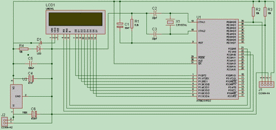
8051 PS2 Keyboard Circuit Diagram
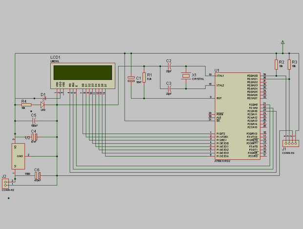
When the source code is examined, it is seen that header files named T_LCD.h and scanning.h are used. The T_LCD.h header file containing the functions required to drive the LCD is given below. Scan.h header file contains scan codes corresponding to each key on the PS/2 keyboard.
Elements Used in the Circuit:
Resistors :
3 pcs 10K
1 pc 8.2K
Capacitors :
2 pcs 22pF
1pc 10UF 25V
1 pc 100UF
1pc 47UF 25V
1pc 470UF 25V
1pc 12Mhz Crystal
1 x Text LCD
1 x 9V battery
Integrated:
1 x 89C51 microcontroller
1 pcs 7805
1 x PS/2 Q keyboard
1pc 40 Leg socket
1pc 14 Leg socket
1 pc dc Jack
Keil and proteus isis ares files to the 8051 PS2 Keyboard project: author: Hakan YALINIZ


Analog to Digital Output Audio Sensor LM386 LM393
Audio Sensor circuit JP1 can set the output as analog or digital “sPlan” chart prepared by the “sprint layout” has been prepared by the PCB file. Robots can be useful for different projects or a circuit
The submission represent experimental module double sonic sensor on the basis of two audio amplifiers and double LM386 comparator LM393
The scheme is quite simple sound sensor and is a standard inclusion of elements. Audio Amplifiers LM393
R5 resistor construction allows it to adjust the threshold comparator operation – sensitivity. Thus at the exit scheme, we get two logical signal – from right and left of microphones. Also, there is an opportunity to process an analog signal directly from the amplifier through the ADC. J1. Options outgoing signals switched through two jumpers in the shoe J1.