FM PLL transmitter circuit 12V supply 500mW has the power circuit PIC16F870 and LMX2306 integrated based on the simple circuit of a single coil are killers though PLL (phase-locked loop-Phase-locked loop) circuits without line would sooner or later will deal though commercially available wound coils can be found
500mW FM PLL transmitter 88-108MHz
Contents
This is strictly an educational project explaining how a transmitter works and can be built. According to the law it is legal to build them, but not to use them. This transmitter is PLL controlled and the frequency is very stable and can be programmed digitally. The transmitter will work from 88 to 108 MHz and the output power is up to 500mW. With minor changes the frequency can be set from 50 to 150 MHz.
FM PLL transmitter Background
FM transmitters have always been fascinating and one can find thousand examples of them on the internet.
Sadly most of them are full of error and miss leading information. Most of them also have low stability and frequency drift, many coils and components which are difficult to find.
The output power is often set to several watts with just a transistor or two…..can’t fool me..
So therefore I decided to construct a simple transmitter with great performances.
Simple construction
Commonly components
High quality and stability
Low number of coils
High output power
The frequency of this transmitter can easy be changed with software and space/compress an air coil, simple don’t you say? The basic hart of this transmitter is a colpitts oscillator. The oscillator is a VCO (voltage controlled oscillator) which is regulated by a PLL circuit and PIC micro controller. Don’t get upset now…it is not that difficult after all. Let’s check the schematic and I will explain the function.
FM PLL transmitter Hardware and schematic
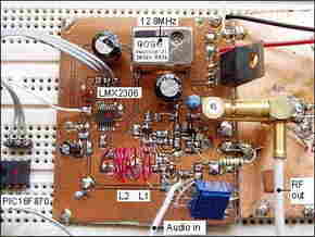
The main oscillator is based around the transistor T1. This oscillator is called Colpitts oscillator and it is voltage controlled to achieve FM (frequency modulation) and PLL control. T1 should be a HF transistor to work well, but in this case I have used a cheap and common BC817 transistor. The oscillator needs a LC tank to oscillate properly.

In this case the LC tank consist of L1 with C1, C2, C3, and the varicap BB139. The coil is parallel with C1 and C2 which are in serial . The same with the varicap and C3. You can think that L is parallel with [ (C1//C2) + (Varicap//C3)] The value of C3 will set the VCO range. The large value of C3 the wider will the VCO range be. Since the capacitance of the varicap is dependent of the voltage over it, the capacitance will change with changed voltage. When the voltage change, so will the oscillating frequency. In this way you achieve a VCO function.
PLL and Microcontroller
The oscillator is made to work as “Voltage Controlled Oscillator” VCO. To control the frequency a synthesizer circuit LMX 2306 has been added. The PLL circuit has a pickup coil (L2) connected to pin 6. This coil should be put close to the L1 coil for picking up some of the oscillating energy. The PLL in the LMX2306 will then use this frequency to regulate the VCO and lock it to desired frequency. The regulating system also need an external reference crystal. In this case I use 12.8 MHz.
At pin 2 of MX2306 you will find a PLL filter to form the Vout which is the regulating voltage of the VCO. The PLL try to regulate the Vout so the oscillator keeps the frequency locked to desired frequency. The desired frequency is programmed into the PIC EEPROM and is clocked into the synthesizer (LMX2306) at power up.
I will below explain how to program the EEPROM for different frequencies. At pin14 of the synthesizer you have a control output. At this output you will find the reference frequency for testing. (I must warn you because the signal is not symetrical in shape. The positive pulse are only a few microsecond so you will have difficult to see it at oscilloscope.) I solved it by connecting it to a 74HC4020 (14-stage Binary Counter) to pin 10 Clock input. At Q0 (pin 9) you will have a symmetrical square wave with half frequency since the circuit is a counter. At Q1 pin 7 it will be divided by 4, see datasheets for more info.
LF input: The audio you wish to transmit should be connected to the Audio input . The signal will affect the varicap and thereby Frequency Modulate FM the RF carrier. A potentiometer P1 has been added to set the modulation depth (Wide FM or Narrow FM). You may have to play a bit with the value of P1 because it tends to modulate to much. You may have to add a 500k – 1M potentiometer instead. You test and find out yourself.
Buffer stage: Here you find another HF transistor and it is working in class C. The resistor R1 and the resistor Re2 set the DC current. In this case I found that 9.1k will give good output power and so the same with 150. If you wish to increase the power Re2 should be lower. You can add another 150 ohm resistor parallel.
In the table below I show you the output power with different voltages and values of resistor Re2.
I advice you not to run this transmitter with to high output power. The transistor I use is a small one and tends to get hot.
I advice you to run the unit from 0 – to 200mW. At 500mW the transistor will be in pain…*smiling*
At the output you will find a T network. This “filter” will match the antenna impedance to the transmitter output stage.
You have two variable capacitors 60pF to tune the transmitter for best performances. The antenna I used I a 1/4 wave whip antenna (wire) about 75cm long. This type of antenna is smaller but not so good performance as a dipole. With a dipole you will be able to transmitter much longer distance.
How long can I transmit?
That is a very difficult question because the environment affect the transmitting distance very much.
In a city environment with concrete buildings the transmitter will send maybe 200m. I an open filed it will transmit 2000m. I did a filed test and with 70mW output power into the “bad” whip antenna placed indoors I could transmit 200-300m out into a park with no problem.
FM PLL Transmitter Circuit Output power
Table below show you the power measurements I have done. The Re2 is 150 ohm and in some test I connect a 50 ohm parallel. The output power in measured into a dummy load of 50 ohm.

FM PLL Transmitter Circuit Testing
The first thing you should test is that the oscillator is working. I disconnected the Vout from pin 2 of the PLL LMX2306. I then connected Vout to ground and check the oscillator. The oscillator should now oscillate at the lowest frequency. With my Wireless frequency counter I found that the oscillator was working at 100 MHz. I streatched the coil L1 a bit until it oscillated at 105 MHz. I then connected Vout to +5V and now the oscillator was oscillating at 108MHz. Great!, just as I wanted. By changing the Vout from 0 to +5V I could change the oscillating frequency from 105 to 108 MHz. I then reconnected the Vtune to the PLL. PIC16F870 programs (INHX8M format) The zip file contains several hex files made for different frequencies (88 to 108) MHz.
Source: hem.passagen.se FM PLL transmitter circuit files:


ATMEGA162 LCD Oscilloscope Circuit
A very nice project cost is a bit high in our country, even hard to find parts Atmel AVR microcontroller series dealing with this type of project is ideal for those who want to learn about
I think part of that is difficult to have the most expensive LCD LMG6402PLF Hitachi LCD Screen LCD Oscilloscope ATMEGA162 microcontroller circuit board have all the details on
Atmel AVR LCD Oscilloscope
FM PLL Senderschaltung 12V Versorgung 500mW hat die Leistungsschaltung PIC16F870 und LMX2306 integriert basierend auf der einfachen Schaltung einer einzelnen Spule sind Killers obwohl PLL-Schaltungen (Phase-Locked Loop-Phase-Locked Loop) ohne Leitung früher oder später zwar kommerziell gehandelt würden verfügbare gewickelte Spulen sind zu finden
500mW FM PLL Sender 88-108MHz
Dies ist ein rein pädagogisches Projekt, in dem erklärt wird, wie ein Sender funktioniert und gebaut werden kann. Nach dem Gesetz ist es legal, sie zu bauen, aber nicht zu benutzen. Dieser Sender ist PLL-gesteuert und die Frequenz ist sehr stabil und kann digital programmiert werden. Der Sender arbeitet von 88 bis 108 MHz und die Ausgangsleistung beträgt bis zu 500 mW. Mit geringfügigen Änderungen kann die Frequenz von 50 bis 150 MHz eingestellt werden.
FM-PLL-Sender Hintergrund
FM-Sender waren schon immer faszinierend und man kann im Internet tausend Beispiele finden.
die meisten von ihnen leider sind voller Fehler und verpassen führende Informationen. Die meisten von ihnen haben auch geringe Stabilität und Frequenzdrift, viele Spulen und Bauteile, die schwer zu finden sind.
Die Ausgangsleistung wird oft mit nur ein oder zwei Transistoren auf mehrere Watt eingestellt.
So also habe ich beschlossen, einen einfachen Sender mit großartigen Leistungen zu konstruieren.