A very nice project cost is a bit high in our country, even hard to find parts Atmel AVR microcontroller series dealing with this type of project is ideal for those who want to learn about
I think part of that is difficult to have the most expensive LCD LMG6402PLF Hitachi LCD Screen LCD Oscilloscope ATMEGA162 microcontroller circuit board have all the details on
Atmel AVR LCD Oscilloscope
The oscilloscope is one of the the most important tools to be used by any electronics hobbyist but not everybody can afford to have one. As commercial scopes are often too expensive, almost every electronics hobbyist thought at a certain time to build one from scratch. The classical oscilloscope (cathode ray tube) is difficult to build at home because of its size, mechanical fragility, high voltages presence, etc. An alternative solution is the modern “PC oscilloscope”, having the advantage of post-processing and recording capabilities, and kind of reduced complexity. However, this solution is often non-portable, expensive (requires an PC) and dangerous for the PC if not isolated from it’s chassis. The third solution, commonly used these days by all commercial oscilloscope manufacturers, is the digital oscilloscope with LCD screen. Therefore, the authors decided to use this solution, and tried to develop it using common parts from today’s component retailers.
Features
Maximum sample frequency: 40MSPS
Maximum input frequency: 5MHz
Maximum displayed frequency without aliasing: 10MHz
Input circuit bandwidth: 20MHz
Display resolution: 240×128 total, trace resolution 200×125
Sensitivity: 40mV/div
Coupling: DC
Input impedance: 10K
Power supply: single DC source 8V..10V, 1A
No incremental mode
Time base: 1s/div, 500ms/div, 200ms/div, 100ms/div, 50ms/div/, 20ms/div, 10ms/div, 5ms/div, 2ms/div, 1ms/div, 500us/div, 200us/div, 100us/div, 50us/div, 20us/div, 10us/div, 5us/div, 2us/div, 1us/div, 500ns/div
Trigger: digitally adjustable
Trace offset: digitally adjustable
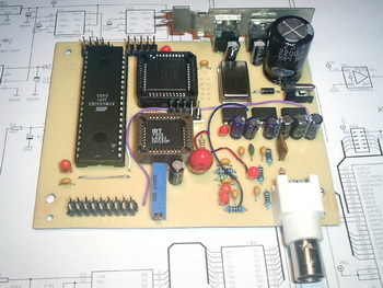
The Input circuit is built with one OPA2652 operational amplifier from Texas Instruments, and together with a low-pass RC filter sets the bandwidth to 20MHz. Additionally, the input circuit handles the vertical trace shift (offset) using the input from a PWM signal generated by the microcontroller (pin 15). The ADC converter is an 8bit ADS830 from Texas Instruments, capable of working up to 60MSPS.
In this design, the ADC works at a maximum of 40MHz, and this clock is generated by the QOS40 (plastic) or QOM40 (metal) oscillator, wich is programmed (divided) through the CPLD circuit (XC9572 from Xilinx). To handle the high throughput of the ADC at high-rate acquisition, the digital output of the ADC is connected to a high speed FIFO memory IDT7201 (512 bytes long) from IDT.
After a full memory buffer is reached, the whole memory content is discarded to microcontroller’s memory, where the samples are further processed and then displayed on the LCD. The microcontroller is an ATMega162 from Atmel, a member of the popular AVR family. The display is a LMG6402PFLR from Hitachi, but any other HD61830B compatible LCD displays can be used (the pinout should be checked for compatibility, of course).
The power supply circuit is built with two 7805 series regulators, and the negative voltages (needed for the LCD and the input circuit) are obtained using three ICL7660A integrated circuits from Intersil.
The PCB is organised as two separate boards: the mainboard and the keyboard. Both of them are designed as single side boards, easy to manufacture using amateur methods. The authors had realised them using the Press’n’Peel method, but any other method can be used if enough accuracy is obtained (SMD parts were used on the board).
source : eosystems.ro/eoscope/eoscope_en.htm
LCD Oscilloscope Circuit files alternative link:


Led light by 220V Operation
220 volts AC mains voltage and low current LEDs can operate with a simple circuit
Das Oszilloskop ist eines der wichtigsten Werkzeuge für jeden Elektronik-Bastler, aber nicht jeder kann es sich leisten, eines zu haben. Da kommerzielle Oszilloskope oft zu teuer sind, dachte fast jeder Elektronikbastler zu einem bestimmten Zeitpunkt, sie von Grund auf neu zu bauen. Das klassische Oszilloskop (Kathodenstrahlröhre) ist zu Hause aufgrund seiner Größe, mechanischen Zerbrechlichkeit, vorhandenen hohen Spannungen usw. schwer zu bauen. Eine alternative Lösung ist das moderne “PC-Oszilloskop” mit dem Vorteil der Nachbearbeitungs- und Aufzeichnungsfähigkeiten. und Art von reduzierter Komplexität. Diese Lösung ist jedoch häufig nicht tragbar, teuer (erfordert einen PC) und gefährlich für den PC, wenn sie nicht vom Gehäuse isoliert ist. Die dritte Lösung, die heutzutage von allen kommerziellen Oszilloskopherstellern verwendet wird, ist das digitale Oszilloskop mit LCD-Bildschirm. Aus diesem Grund entschieden sich die Autoren für diese Lösung und versuchten, sie unter Verwendung gemeinsamer Teile der heutigen Einzelhändler zu entwickeln.
Maximale Abtastfrequenz: 40MSPS
Maximale Eingangsfrequenz: 5 MHz
Maximal angezeigte Frequenz ohne Aliasing: 10MHz
Bandbreite der Eingangsschaltung: 20 MHz
Anzeigeauflösung: 240 × 128 insgesamt, Trace-Auflösung 200 × 125
Empfindlichkeit: 40 mV / div
Kupplung: DC
Eingangsimpedanz: 10K
Stromversorgung: einzelne Gleichstromquelle 8V..10V, 1A
Kein inkrementeller Modus
Zeitbasis: 1s / Div, 500ms / Div, 200ms / Div, 100ms / Div, 50ms / Div, 20ms / Div, 10ms / Div, 5ms / Div, 2ms / Div, 1ms / Div, 500us / Div, 200us / Div div, 100us / div, 50us / div, 20us / div, 10us / div, 5us / div, 2us / div, 1us / div, 500ns / div
Abzug: digital einstellbar
Spurversatz: digital einstellbar