
Control of a 108kHz ultrasonic water atomizer with PIC12F1840. A high-power nebulizer crystal circuit is designed to operate 3 atomizers simultaneously. The ultrasonic water atomizer device has 3 different operating modes. Source assembly and hex codes are available. With this circuit, you can build your own nebulizer and humidifier.
Water is atomized using a ceramic ultrasonic piezoelectric transducer. The atomizer exits through small holes at the top. A cotton swab moistened with water is inserted into the bottom. The water “bubbles” / “atomizes” to a height of approximately 20 to 30 cm. During atomization, an alternating voltage of 108 kHz is applied to the piezoelectric transducer.
The high frequency of 108 kHz is very precisely adjusted by the control program. The PIC12F1840 produces a stable and symmetrical square wave signal. The frequency was measured as 107.9 kHz using an oscilloscope and frequency meter.
Atomizer Control Circuit Operation
Contents
Pressing the button continuously switches between four different modes:
Mode 0: Sprays continuously.
Current consumption is measurable in this mode. In modes 1 through 3, there is a very short interruption every 50 ms due to time interruption and program pause.
Mode 1: Sprays at longer intervals. Intervals can be changed in the ASM program.
The current output is as follows:
SPRAY_TIME1 EQU D’3′ ;SECONDS * NUMBER –>NOW 3 SECONDS
PAUSE_TIME1 EQU D’2′ ;SECONDS * NUMBER –>NOW 2 SECONDS
Mode 2: Sprays at short intervals. Intervals can be changed in the ASM program.
Current value:
SPRAY_TIME2 EQU D’4′ ;IN 50MSEC * NUMBER –>NOW 200MSEC
PAUSE_TIME2 EQU D’10’ ;IN 50MSEC * NUMBER –>NOW 500MSEC
Mode 3: This is designed to simulate the operating process of a steam locomotive. It sprays steam at intervals with variable pauses and spray durations. When the cycle is complete, it restarts after a pause. This pause duration can be set in the ASM program at the end of the cycle.
CYCLE_PAUSE EQU D’100′ ;IN 50MSEC * NUMBER
NOW 50MSEC * 100 = 5000MSEC = 5SEC.
When Mode 3 is reached and the button is pressed again, it restarts from the beginning with Mode 0. The device remembers the selected mode when it is switched off. When restarted, it starts operating again in this mode.
Caution: The piezo sensor gets very hot if operated without water!!!
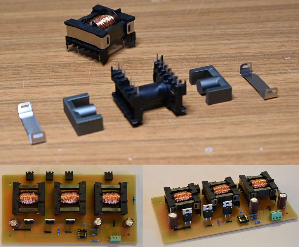
About the ETD29 Transformer
When winding the ETD29 transformer, only the number of turns is important. The diameter of the enameled copper wire is almost irrelevant. 0.3 mm enameled copper wire is used.
The wire should be on a spool. This makes hand winding easier. You don’t need to pay attention to the starting position or winding direction. First, a 37-turn primary coil is wound onto the transformer.
Then, a 220-turn secondary coil will be wound on top of it. However, you need to compare the assembly diagram to determine which pins you need to cut from the transformer, i.e., which ones you should use.
Using an ohmmeter, the resistance of the primary winding was measured as 0.4 ohms, and the resistance of the secondary winding as 2.3 ohms. This measurement is not a guarantee; it is only a guideline.
Piezo Sprayer
The connection points of the piezo ultrasonic sensor are the red and black wires. You don’t need to pay attention to polarity in this circuit.
You should not reverse the top and bottom parts of the sensor. The top part, where the spray occurs, is where the red or black wire is soldered to the sensor.
A cotton swab soaked in water is pressed against the transmitter at the bottom.
The power cable is extended up to 40 cm using a double-core cable (multi-strand cable).
However, it should not be too long.
Otherwise, the spray will be less noticeable.

About MOSFETs
You can use IRF3708 or IRL2505 type MOSFETs. Both have a forward voltage of approximately 1.5 V.
The edges are steeper at 108 kHz. The IRF1010 gave worse results. (Ugs = approximately 3.3 volts) The steeper edges are visible not only on the oscilloscope but also due to higher effective current consumption.
“Low-quality” MOSFETs like the IRF1010 have lower current efficiency.
Atomizer Nebulizer Control and Power Supply
In my initial tests, a 12V/1.5A power supply was used, reduced to 5 volts with the µA78S05, but the 7805 power was insufficient, only operating one piezo transducer. A more powerful 5-volt source is needed for three.
In tests performed without the PIC12F1840 control unit installed, current can flow when the MOSFETs are touched.
Therefore, when a positive voltage is applied to the MOSFET gate, current flows through the MOSFET and transformer.
Without the 108kHz AC voltage (from the control unit), the pure ohmic resistance of the transformer’s primary coil is approximately 0.4Ω. This causes a short circuit.
To prevent a positive voltage from being applied to the MOSFET gate, a 10kΩ resistor is connected to ground.
This is only necessary when the control unit is not in the socket and therefore the 108kHz AC voltage is not present.
Nebulizer Air Humidifier Circuit Diagram

Source: dl3ukh.de/Bastel-Ultraschall-Wasser-Zerstaeuber.htm


