1100w SMPS power supply with all the details transformermeister formulas power cycles, 230v filter, MOSFET calculations uc3825 PWM control entegrs information about the output diode accounts dc filter capacity calculations of the other components of electronic accounts temperature cycle cooler account performance metrics have everything schematics and PCB drawings available small a problem can be solved to translate with google translate German language, but technically that’s not a good translation.
Finally, more than half have not tried yet, but I’m more opportunity to review feedback on the changes to the circuit when viewed with 2 × 55 volts logout trafosu ETD49 you think you can run 2x secondary wound
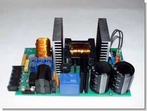
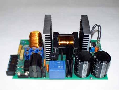
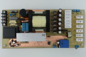
1100w SMPS Switch mode power supply Project

Switching Power Supplies (SNT) to solve increasingly from conventional power supplies.
The advantages lie in the high power density, low weight and the potential Integration of protective measures such as a short-circuit protection. Especially at high Output power is the use of a SNT’s, despite the complex structure makes sense, since Construction equipment and weight compared to conventional power supplies drastically reduced will.
The required components are, thanks to modern manufacturing techniques and comparatively easy inexpensive to obtain. In this project the students deal with the development and manufacture a constant voltage source with an output voltage of 55V and an output of 1.1 kW. The supply unit will serve as a switching power supply running. It is used to power a UPS (Uninterruptible Power Supply) in the online operation. Online means here that the sinusoidal output voltage (230VRMS) constantly on the DC voltage fed inverter can be generated. The supply switching power supply must therefore the full output of the UPS facility and correspondingly powerful design be. Buffer battery, directly connected to the output of the SNT’s are connected, is Power failure the inverter will be uninterrupted energy supplies.
Mechanical requirements
• Expected mechanical dimensions of 200mm x 160mm x 95mm (lxwxh) can not exceed.
• The direction of departure of output terminals is determined.
• The position of the fan to cool the power electronics is determined.
• The mechanical criteria are defined as the power adapter into an existing housing
Electrical requirements
• The power source must be short circuit proof.
• The output voltage should UAUS DC 55V ± 2%.
• The maximum output current is 20A is IAUS.
• The minimum output current is 0.7 A. IAUS_min (Minimum input current of the inverter)
• The maximum output power is 1.1 kW PAUS.
• The efficiency should not fall below 0.9.
• The input voltage UEIN is 230V AC + 10% and – 20% at 50 – 60 Hz
• Thermal overload protection with a maximum ambient temperature of 45 ° C.
Selection
- 2.1 Principle of switching circuits Mains adapter
- 2.1.1 Single-Flyback Converter
- 2.1.1.1 Prinzipschaltbild Figure
- 2.1.1.2 Advantages
- 2.1.1.3 Disadvantages
- 2.1.2 Single-
- 2.1.2.1 Prinzipschaltbild Figure
- 2.1.2.2 Advantages
- 2.1.2.3 Disadvantages
- 2.1.3 Push-pull Durchflußwandler
- 2.1.3.1 Prinzipschaltbild Figure
- 2.1.3.2 Advantages
- 2.1.3.3 Disadvantages
- 2.2 Elected circuit
- 3 At ASKED THE PROJECT requirements
- 3.1 Mechanical requirements
- 3.2 Electrical requirements
- 3.3 anticipatory calculations
- 3.3.1 Input Voltage
- 3.3.2 Input Power
- 3.3.3 Input current
- 3.3.4 intermediate circuit voltage
Selection AND KEY DATES OF THE COMPONENTS AND 11 Heatsinks
- 4.1 Input fuse
4.2 Stromkompensierte Entstördrossel
4.3 Input rectifier
4.3.1 Dissipation Calculation
4.3.2 Dimensioning of the heatsink
4.4 DC bus capacitor
4.5 Inrush current limitation
4.5.1 Surge in cold NTC’s
4.5.2 Surge in hot NTC’s
4.5.3 Review of the border last integral
4.6 Interpretation of Gegentaktübertragers
4.6.1 Selection and characteristics of Übertragerkernes
4.6.2 Power Dissipation
4.6.3 Calculation of the minimum primary turns
4.6.4 Calculation of secondary windings
4.6.5 Determination of the actual ratio
4.6.6 Calculation of the maximum primary current
4.6.7 Determination of the wire cross-sections
4.6.7.1 Primary wire cross-sections
4.6.7.2 Secondary wire cross-sections
4.6.8 Determination of the copper losses of the Gegentaktübertragers
4.6.8.1 Mean Windungslängen and effective wire cross-section
4.6.8.2 copper losses of the primary winding
4.6.8.3 copper losses in the secondary winding
4.6.9 Wicklungsaufbau of the transformer
4.7 Push-pull transistors
4.7.1 Dielectric strength
4.7.2 Durchlaßverluste
4.7.3 Switching losses
4.7.3.1 losses through the output capacity of
4.7.3.2 Kommutierungsverluste
4.7.4 Total power dissipation of the push-pull switch
4.7.5 Determination of the heatsink for the push-pull switch
4.8 Dimensioning of the temperature switch
4.9 Output Rectifier
4.9.1 Minimum Blocking Voltage
4.9.2 consideration of the losses
4.9.2.1 Comparison of the data values
4.9.2.2 Calculation of Losses
4.9.3 Determination of the heatsink for the output rectifier
4:10 dimensioning of the storage choke
4.10.1 Calculation of the necessary turns
4.10.2 Calculation of the maximum Durchflutung
4.10.3 Calculation of the copper losses
4.10.4 Calculation of iron losses
4:11 sizing of transformers for voltage control production
4.11.1 Calculation of the required power control gate
4.11.2 Power consumption of the control electronics
4.11.3 dissipation of the voltage 7815
4.11.4 Required performance of the control transformers
4:12 baseload power dissipation of
4:13 Fans
5 CALCULATION OF THE TOTAL LOSS
5.1 Addition of sub losses
5.2 Calculation of the efficiency
6 POWER PROJECT DESCRIPTION AND OPERATION PLAN
6.1 SCM plan
6.2 Functional Description
6.2.1 Path of energy
6.2.2 Pulsbreitenmodulator
6.2.3 Voltage
7 Notes ON THE PWM module UC 3825
7.1 The block diagram of the UC3825
7.2 Description of functional blocks
7.2.1 Function Block 1: Error Amplifier
7.2.2 Function Block 2: PWM comparator
7.2.3 Function Block 3: Oscillator
7.2.4 Function Block 4: Or 32 Link
7.2.5 Function Block 5: Latch for PWM generation
7.2.6 Function Block 6: Toggel-Flipflop for generating the push-pull signal
7.2.7 Function Block 7: Output Drivers
7.2.8 Function Block 8: overcurrent detection
7.2.9 Function Block 9: Control of Supply
7.2.10 Function Block 10: Generation of reference voltage
7.2.11 Function Block 11: Softstarteinrichtung
7.2.12 Function Block 12: Internal auxiliary power generation
7.2.13 Function Block 13: Monitoring of the reference voltage
7.2.14 Function Block 14: Activation of the device
8 PCB DESIGN AND PLACEMENT OF COMPONENTS
8.1 Treatment of tension distances
8.2 Layout’s
8.2.1 Layout of the Components page
8.2.2 Layout of the solder
8.3 BOM and assembly Prints
8.3.1 BOM
8.3.2 Assembling the mounting pressure Page
8.3.3 solder mounting pressure from the
9 INSTALLATION
9.1 Listing of the used instrumentation and tools
9.2 Commissioning measurements
9.2.1 Review of control signals
9.2.2 Investigation of the output voltage at idle and under nominal
9.2.2.1 Height of the output voltage
9.2.2.2 Output ripple
9.2.2.3 Structure of the output when you turn
9.2.3 Recording of the currents and voltages to the push-pull switches
9.2.4 Measurement of the output current of the input rectifier
9.2.5 Recording performance and efficiency of the power supply
9.2.5.1 Measuring the Power
9.2.5.2 Review of the efficiency
9.3 Thermo Graphic recording nominal
9.4 Lessons learned
10.1 Bibliography
10.2 List of Figures
Source : gb97816.homepage.t-online.de 1100W 55V 20A SMPS Circuit UC3825 Switchmode Power Supply schematic pcb alternatif link


PIC16F876 Midi splitter Circuit with LCD display
Circuit pic16f876 microcontroller and SN74LS00 NAND gate integrated based on the midi input CNY17 opto Kubla with disabled insulated isolated single midi signal 2 as output enlarge able 2 × 16 LCD screen on the selected channel information can be seen software in assembly language prepared pic audio Signals processing in can be an example
Midi splitter Project
What’s the password for the 1100W power supply
Hi,
Pass: 320volt.com