Battery level indicators added later to 3S 25A BMS boards used in cordless drill batteries may seem like harmless modules that draw very low current at first glance. However, when the indicator module is connected directly to the BMS output, it may create a small continuously connected load from the perspective of the protection circuit. This can make it difficult for the board to return to normal after the discharge protection is activated.
The purpose here is not to completely cancel the battery level indicator, but to rearrange the supply of the indicator so that it does not keep the BMS protection logic busy.
The previous BMS modification article about the BMS 3S 25A circuit schematic and modification can also be reviewed.
Why does the problem occur?
Contents
When the battery indicator module draws around 123uA current at approximately 12.6V, this current may be perceived by the BMS as a continuously connected load of about 100kΩ.
For this reason, when protection is triggered, a load is still seen on the output side, and in some cases the board may not fully recover without connecting a charger.
This situation becomes more noticeable especially in packs that remain unused for a long time or in applications that approach the deep discharge limit.
To examine Li-ion protection logic in a general framework, see the article about Li-ion battery protection structures.
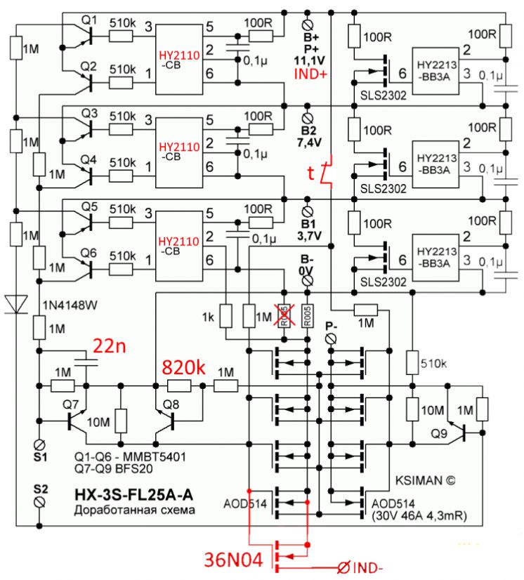
Modified 3S 25A BMS circuit schematic
What does the modification provide?
As a solution, a separate negative output is created for the battery indicator apart from the main P- line.
This new line is shown as IND- in the schematic. Thus, while the positive terminal of the indicator module remains at the pack positive, its negative terminal is connected not directly to P-, but to the IND- line created through the added MOSFET.
When protection is activated, this additional line also turns off and the indicator module is completely disconnected from the circuit.
As a result, the battery indicator no longer creates a continuously connected fake load at the BMS output.
This provides a more logical solution especially in applications where users prepare their own packs or add an indicator to a Li-ion battery pack.
Main sections in the schematic
| Section | Highlighted components | Function |
|---|---|---|
| Cell protection monitoring section | HY2110-CB, Q1-Q6 | Monitors the voltage status of each cell group and forms the basic decision chain for overcharge and overdischarge protection. |
| Cell balancing section | HY2213-BB3A, SLS2302, 100R, 0.1uF | Manages the balancing behavior in cells approaching the end of charge. |
| Main power switching section | AOD514 MOSFET group | Controls the charge and discharge path by switching the main negative line of the pack on and off. |
| Additional switching for the indicator | 36N04 | Provides a separate IND- line to the battery indicator, ensuring that the indicator is completely disconnected during protection. |
| Auxiliary control and timing section | Q7-Q9, 22nF, 820k, 1N4148W | It is the auxiliary switching and timing section that shapes the control behavior of the added indicator line. |
What do the main components used in the circuit do?
The three HY2110-CB units in the schematic operate in the single-cell protection IC class and are located in the section that monitors each series cell point separately.
HY2213-BB3A is an IC designed for cell balancing, and its OUT output is used in the balancing MOSFET drive logic.
The AOD514 MOSFET group controlling the main negative line forms the low-resistance power switching side.
The BFS20 transistors around Q7-Q9 should not be considered as power switches carrying the main current, but as auxiliary small-signal control elements.
Therefore, when describing this section, the expression “auxiliary control stage” is more accurate instead of “power transistor”.
Why is the connection logic changed?
Normally, when the negative line of the battery indicator is connected directly to the P- terminal, the module remains continuously at the BMS output.
In this modification, the indicator negative line is moved to the newly created IND- point.
Thus, the indicator is active only as long as protection allows it.
This small difference is important in practice. Because while the drill motor continues to use the line supplied from the main power MOSFET group, the indicator module no longer keeps the protection chain unnecessarily busy.
Application notes
- The negative terminal of the indicator module should not be left on the old P- connection; it should be moved to the newly created IND- line.
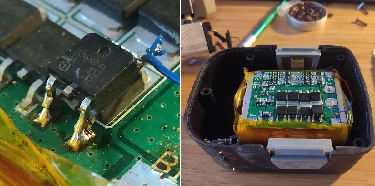
- When soldering the added N-channel MOSFET, pad width, heat dissipation, and mechanical strength must definitely be taken into account.
- The 22nF and 820k values around Q7-Q9 should not be changed blindly, as they are located in the section that affects behavior.
- In this type of modification, not only the electrical connection but also the board layout and soldering quality directly affect the result.
- Tests should first be performed with a current-limited power supply or careful observation.
Oscilloscope Measurements
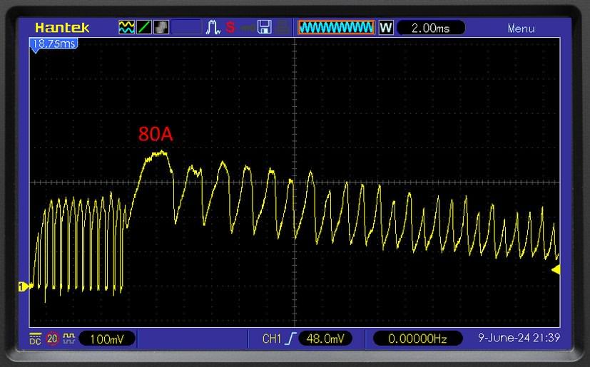
In the shared measurements, it is seen that high current is drawn at startup, while a lower but continuous operating current occurs under full trigger.
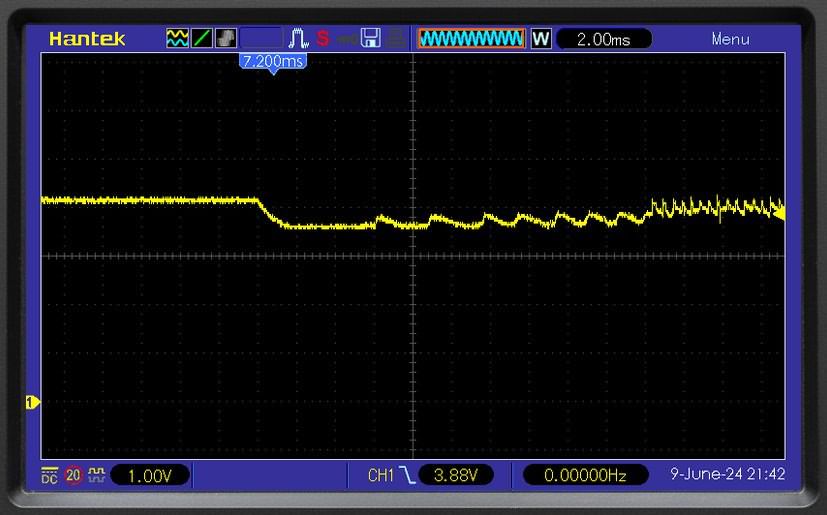
A noticeable drop in battery voltage at the moment of starting is an expected situation in drill motors.
The important difference here is that after the modification, the battery indicator line no longer remains in the circuit in a way that disrupts the protection behavior.
Startup current oscilloscope image
Operating current oscilloscope image

In the operating current section, the change in PWM behavior when the trigger is fully pressed shows that the circuit switches to a different operating mode according to load and drive conditions. For this reason, startup, full load, and protection moments should be evaluated together, not by looking at only a single oscilloscope screenshot.
Battery voltage at the moment of operation
This modification creates a more correct supply point for the battery level indicator without disrupting the basic protection logic of the 3S 25A BMS board.
The main idea is simple but effective: the indicator module should not remain as a continuously connected small load at the BMS output.
Thanks to the IND- line created with the added N-channel MOSFET, the indicator turns off together with the protection, and the tendency of the board to remain unnecessarily locked is reduced.
Especially in 3S cordless drill batteries, a more predictable and trouble-free use can be achieved with a small intervention.
Source: mysku.club/blog/diy/100339.html