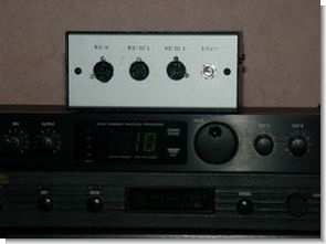
Circuit pic 16f876 microcontroller and SN74LS00 nand gate integrated midi input with CNY17 opto coupler, it can reproduce the isolated isolated single midi signal as 2 outputs. Selected channel information can be seen on the 2×16 LCD screen. could be an example.
Since we chose a flexible PIC running at 4 MHz, the resulting circuit is pretty simple because all the dirty work is done by the firmware. Following the schematic circuit it can be noted that the MIDI IN input is used to directly feed an optocoupler.
This device plays the role of protection against potentially dangerous voltages, but much more importantly, it prevents ground loops from forming between different instruments.
In terms of communication protocol, commands are sent via packets (messages) generated by a header, a body, and a terminator. There are 16 channels for messages for each physical connection.
For example, a musician might play a piano associated with channel 0, a violin on channel 1, a viola on channel 2, a cello on channel 3, and so on. can use. In this way, every note played over the MIDI interface will be played by the right instruments according to the channel in which it is used.
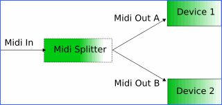
What we want to talk about in this article is a project using PIC16F876, which can split the MIDI message into two different outputs depending on the channel. So this circuit has one input and two outputs. For each received message, it should recognize the channel and guide it by following a table kept in memory.
A similar project is useful for those like me who own a few MIDI instruments but only have a simple computer interface with one physical output. This circuit can actually be used to control two devices independently.
Midi splitter Project
The MIDI protocol has been a widely used standard in the music field for some time. Its purpose is to allow electronic devices to communicate between them. Examples include master keyboards, extenders, synthesizer, effects generators, and much more.
Introduced in the early 1980s, this system has spread widely thanks to its unique advantages and low cost. Some kind of MIDI interface can be found in almost any electronic instrument that is little more than a toy. It is an asynchronous serial communication protocol operating at 31.25 kbit/s (which is quite low for current standards such as FireWire or USB).
From a user’s point of view, a MIDI interface is similar to two female 5-pin DIN connectors, designated IN and OUT, and often the third is called THRU. The input port (IN) is a receiver for messages that tell which notes should be played with which instruments.
The output (OUT) is obviously symmetrical. To connect a keyboard equipped with a MIDI interface with an audio expander, you must connect the OUT port of the keyboard to the expander.


source : davbucci.chez-alice.fr/index.php?argument=elettronica/midi_splitter/midi_splitter.inc PIC16F876 Midi splitter Circuit with LCD display schematic source code Alternative link:


PIC18F452 CCS C RF Humidity Temperature Circuit (addition to calendar, clock)
Feature a very high level transmitter and receiver circuit consists of two parts of a project are provided with the main control PIC18F452 PIC16F84 sensors are connected to the transmitter circuit based on the information received from sensors on the lcd screen is displayed as text and graphical
MPX4115 pressure sensor TC77 SPI temperature sensor H1 humidity sensor wireless RF communication RX + TX433 modules used also DS1307 RCT and 24C256 i2c EPROM entegreleri in the project used the software CCS C (PCWH CCS compiler) prepared with source c code eagle pcb schema files located in the heat, humidity , pressure calibration settings explained.