UC3825 high speed PWM control IC based on the SMPS circuit 24v output gives power 18 about 430W fan without using a large cooler longer with 10 amp can give 18 amps for the fan and the cooling should be done MOSFET and the output diode printed circuit board underneath are being installed for the project circuit diagram and sprint PCBs have prepared with layout drawings.
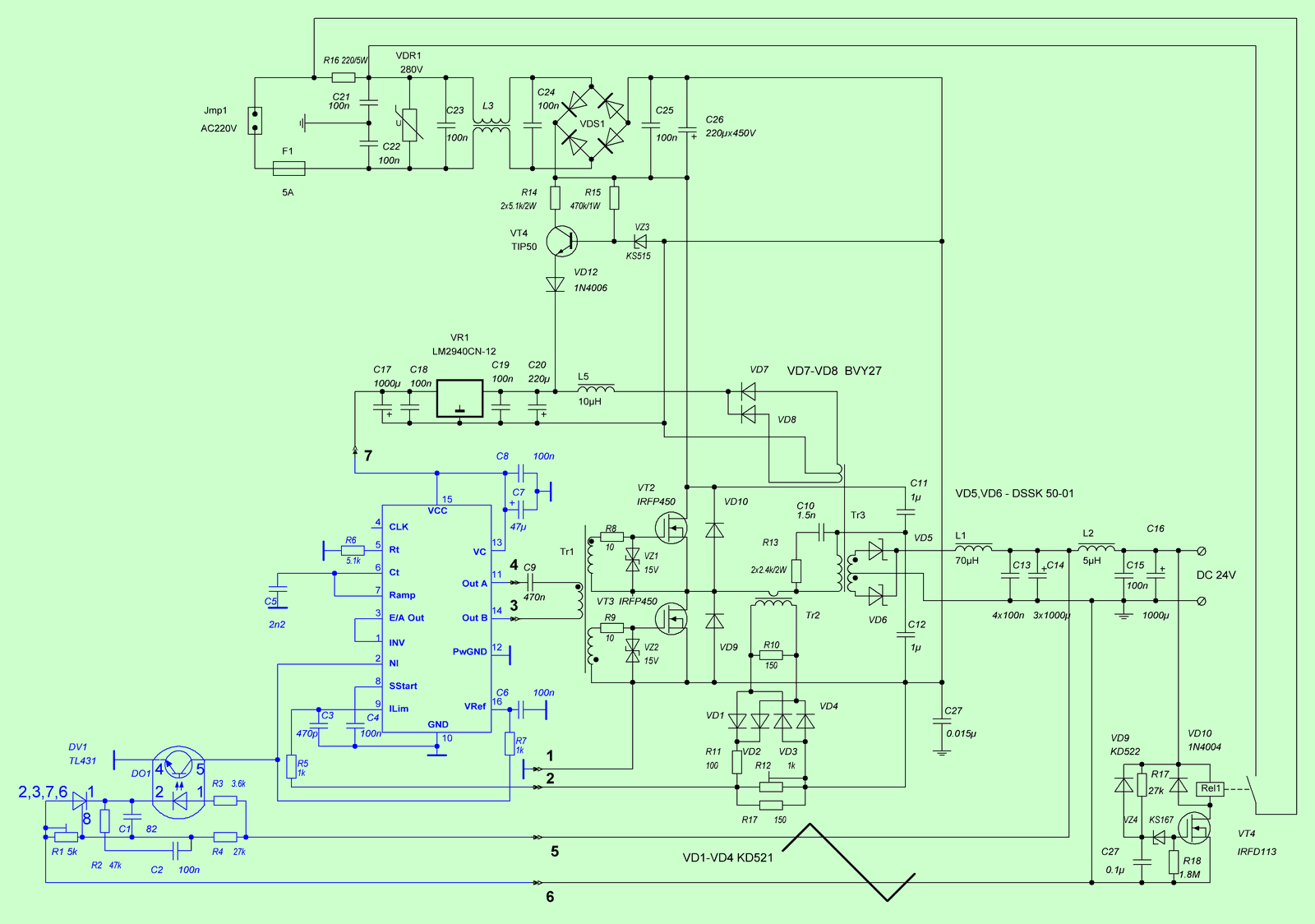
Switching power supply 24V 18A Schematic
The switching power supply is designed for an output voltage in the range of 20-28V, with a maximum long-term load current of 10A without forced cooling and up to 18A when using a fan. The UC 3825 chip, which is widely used in industrial devices, is used as a controller. Its choice was determined, first of all, by the availability. Well, since it is (along with 3525) the industry standard, then it didn’t take long to think.
The power supply is a typical half-bridge with optocoupler isolation OS voltage. Current protection is carried out using a current transformer.
The features include increased requirements for installation and design. There are several reasons. Firstly, the applied controller has a high limiting operating frequency, the control inputs of the controller are quite high-impedance and sensitive to pickups. This obliges you to follow some rules for installing such a controller and tying it. Secondly, the specifics of the use of this PSU made strict requirements for various interferences, both radio frequency and acoustic. The latter imposed a restriction on the development of the design, in particular, on minimizing the dimensions and placing some components. The frequently used “computer” arrangement of power elements and radiators was excluded, as well as the use of components designed for operation mainly in the blowing mode, that is, without a noticeable margin in terms of parameters.
The BP scheme can be divided into three parts. The first is the input power circuits containing an anti-interference filter, a varistor and a power filter capacitor charge surge current limiter, consisting of a resistor R 16 and a simple time relay on a VT 4 transistor. The second is the controller node, highlighted in blue. And the third, power, converting part, with a filter at the output.


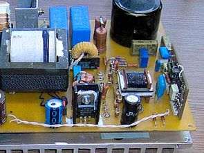
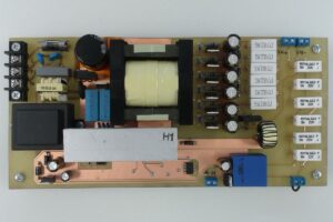
On printed circuit boards, parts are not marked, but given the simplicity of the design, it is not difficult to determine their compliance with the circuit diagram.
The circuit is assembled on two printed circuit boards, the main and sub-board of the controller. So it was possible to solve the problem with the sensitivity of this microcircuit to various kinds of pickups. Please note that the controller sub-board is double-sided, SMD components are mounted on one side, and the other side is in the form of a continuous foil, used as a common wire and shield. Capacitor C6 is installed by surface mounting, on top of C7.
Winding Transformer components data:
Transformer Tr1 is wound on a N67 ferrite core 26x6x6 in size and contains 3×16 turns of PELSHO 0.35 wire.
Tr2 is made on the same ferrite, the core size is 42x10x20, the primary winding is made with a 0.08 wire litz wire and a total twist diameter of 1 mm, with a total silk insulation and contains 17 turns.
Secondary winding – 2×5 turns of copper tape 0.4 thick and 12 mm wide.
Auxiliary winding for powering the controller contains 2×3 turns of PELSHO 0.35 wire
Choke L1 on a ring made of sintered mopermalloy, permeability 63. Ring dimensions 28x15x15, protective coating color – yellow, with a white end. The number of turns is 25.
The current transformer is used ready, the primary winding is a MGTF wire passed into the ring hole with a core diameter of approx. 1.5mm.
Secondary – approximately 150 – 200 turns of wire on the M16x8x6 ring, permeability is about 2000.
L2 inductor is ready, on a ferrite rod, wire diameter is 2mm.
The chokes of external filters are made on a ferrite core with high permeability (4000), when winding them, the windings should be correctly positioned to prevent core bias – for this, each half-winding is wound on its own half of the ring, and the direction of the windings must be antiphase.
It should be noted that often, the use of certain details was determined by their presence, and not by the mandatory need to use this particular component. When repeating the UPS, this should be taken into account.
Pay attention to the mandatory connection of the capacitor C27 to the radiator housing. Otherwise, parasitic oscillations may occur. Relay Rel1 any, operating voltage 24V and current through the contacts is not less than 3A.
Source: qrz.ru Alternative link:


Decimal Binary Hexadecimal Calculator and Converter Program
Hex, bin, dec converter calculation program the microcontroller and for different applications available also in C #, Visual Studio. Net 2005 source code are exe-packed program portable is running (Net framework 2.0 or higher is installed should be).
Hello my name is Ella want a circuit diagram of 20v 15a SMPS guys help me i have very important project please!
Hello Ella,
You can use this circuit. R1 (5k) voltage adjustment R12 (1k) current adjustment