Staircase light switch with 2 different trigger modes. The circuit functions as a classic staircase light switch. When the supply voltage (230V AC) is applied, the system enters standby mode, and the connected bulb does not light up during this phase. An external button must be pressed to activate the bulb.
When the button is pressed, the bulb lights up for approximately 3 minutes. If the button is pressed again before this time is up, the bulb switches off.
The lamp switches off automatically when the time is complete. Thanks to this operating principle, the circuit performs both on/off (flip-flop) and time-delayed shutdown functions simultaneously.
As an additional advantage, multiple buttons can be connected in parallel to a single control line.
Staircase Lighter Basic Technical Specifications
Contents
Operating time: approximately 3 minutes
Triggering: upon pressing or releasing the button
Supply voltage: 230 V AC
Total power of connectable lamps: 500W
The Staircase Lighter circuit does not require an additional power supply or adapter to operate. The low DC voltage required for system operation is provided by the Transformerless Power Supply method.
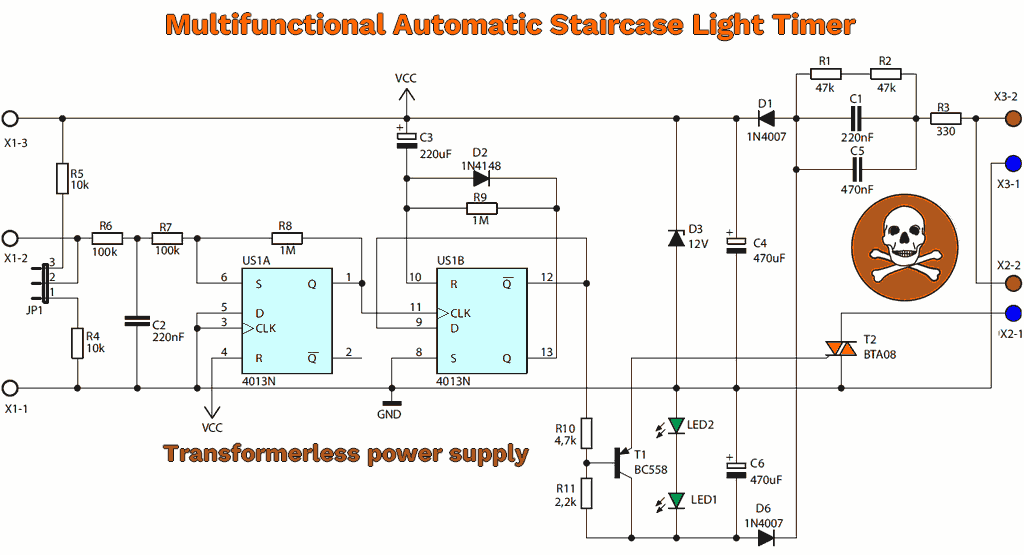
500W Staircase Lighter Circuit Diagram
Staircase Automatic Switching Circuit Operating Principle
At the heart of the system is the CD4013 integrated circuit, containing two D-type flip-flops.
One of these flip-flops (U1A) is used in an unusual way, acting like a Schmitt trigger.
Hysteresis is provided by resistors R7 (100kΩ) and R8 (1MΩ), while resistor R6 (100kΩ) and capacitor C2 (220nF) act as filters to suppress interference and unwanted signals that may occur in long cables.
When the button is pressed, a rising edge is created at the CLK input of the flip-flop.
Since this structure operates as a toggle, the output state is inverted with each button press.
In the normal state, the CD4013 “Q” output is at a low level and capacitor C3 is charged.
Each time the CD4013 “Q” output switches to a high level (pin 13 of the CD4013), the BTA08-600C triac is triggered, and simultaneously, the discharge process of the C3 220µF capacitor begins through the R9 1MΩ resistor.
When the voltage across the capacitor exceeds the logic threshold of the reset input (pin 10 of the CD4013), the flip-flop is reset, the triac closes, and the lamp is turned off.
The BTA08-600C triac driving circuit may seem unusual at first glance; however, it is quite suitable for this application.
The power supply for the circuit provides a 12V Zener positive voltage for the digital section via D1 1N4007, C4 470µF, and D3, while the low-level negative voltage for the triac triggering circuit is provided by D4, D5, D6 1N4007, and C6 470µF.
Although this negative voltage level is small, it is sufficient to trigger the triac.
When the flip-flop’s inverted output (pin 12) is at a logic “1” level, a positive voltage is applied to the base of the T1 BC558 transistor, and the transistor remains in cutoff.
When the output level changes, the transistor switches to the conduction state, initiating the triac triggering process.
Circuit Assembly and Settings
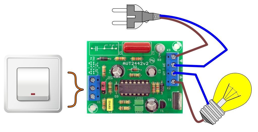
Capacitors C1 and C5 are used to reduce the 220V mains voltage. You can use one 680nF capacitor instead; if you can’t find one, the PCB design is made to connect two capacitors, 220nF and 470nF.
Assembly is not complicated; however, since the circuit operates directly with the mains voltage, all connections must be checked very carefully before the first energization.
Otherwise, component damage or serious safety risks may occur.
A circuit built with robust components of the correct values will work without requiring additional adjustments.
If necessary, the closing time can be adjusted as needed by changing the values of C3 between 1µF and 4700µF and R9 between 10 kΩ and 4.7 MΩ.
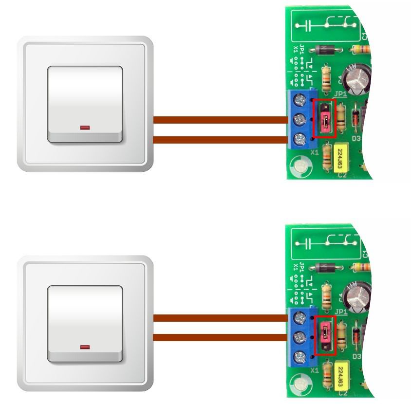
The JP1 jumper is used to select the triggering method:
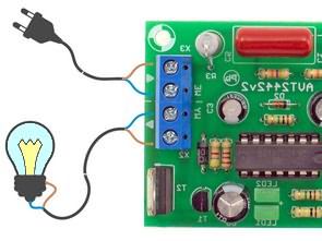
When JP1 is in position 1-2 and the button is connected to terminals X1-2 / X1-3, the circuit is triggered when the button is pressed.
When JP1 is in position 2–3 and the button is connected to terminals X1-1 / X1-2, the trigger occurs when the button is released.
The completed device must be placed in a suitable and insulated enclosure to ensure user safety.
It should also be noted that the control cables and buttons connected to the X1 connector may also be exposed to mains voltage.
Therefore, electrical safety rules must be strictly followed during assembly and use.
Note: The PCB layout of the Staircase Lighter circuit was copied using Sprint layout 6. It has been checked but not tested.
WARNING: This circuit operates with high voltage. Be careful and pay attention to the capacitor connections. Reversing the + and – poles can cause large explosions at high voltage. Before operating the circuit, use a fused electrical line and protective goggles.
souce: sklep.avt.pl/pl/products/automatyczny-wylacznik-czasowy-automat-schodowy-kit-avt-2442-165453.html


