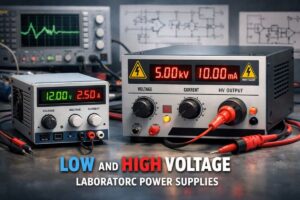
Different types of power supply projects developed for laboratory and experimental electronics applications. These projects, ranging from low-voltage symmetrical power supplies to high-current-capacity laboratory supplies and special power supplies that generate high voltage, cover a wide range of applications required in testing, measurement, R&D, and maintenance-repair work.
All shared power supplies are provided with full documentation so that users familiar with the electronic design process can examine and improve them. For all of the projects, the following are available:
PCB and schematic source files prepared with the PCAD program,
PDF schematic and printed circuit board outputs taken from these files,
Panel source files drawn with CorelDRAW for enclosure front panel designs,
In addition, PDF outputs of the front panel drawings are available.
0-250V DC 5V DC High-Voltage Power Supply
Contents

It is a compact power supply designed for electronic applications requiring high voltage (Opamp, transistor structure). It can be used safely in testing, experimentation, and development work where different voltage levels are required.
Technical Specifications
- Number of output channels: 2
- Channel 1 output: +5 V / 250 mA
- Channel 2 output: 0…+250 V / 10 mA
- Short-circuit protection: Available
- Output voltage indicator: LED indicator
- Supply voltage: 220 V AC ±%10, 50Hz
Applications
It can be used in applications such as photodiode power supplies, electronic tubes (vacuum tubes), zener diode and varistor tests. It is also preferred in R&D work, educational experiments, and maintenance-repair processes of electronic devices. All outputs are protected against short circuits, and active output voltages can be monitored with LEDs.
Multi-Output Low-High Voltage Laboratory Power Supply

It is a multi-channel, universal laboratory power supply designed for circuits requiring both low and high voltage. (78xx, 79xx, LM317, Transistor based)
Technical Specifications
- Number of output channels: 4
- Channel 1: ±5V / 0.8A
- Channel 2: ±15V / 0.3A
- Channel 3: +12V / 1A
- Channel 4: +30…+180V / 0.1A
- Short-circuit protection: Available
- Output voltage indicator: LED
- Power supply: 220 V AC ±%10, 50Hz
- Dimensions: 150 × 90 × 22 mm
It is a flexible power supply that can be used in laboratory environments, scientific experiments, electronic design and repair work, as well as in industrial applications. All outputs are protected against short circuits, and active voltages can be monitored from the front panel.
On the front panel: Main power switch, Operation LED, Load connection terminals, Output voltage LEDs, Adjustment potentiometer for the 30…180 V channel
On the rear panel: Mains cable and ground connection are located.
Symmetrical Laboratory Power Supply
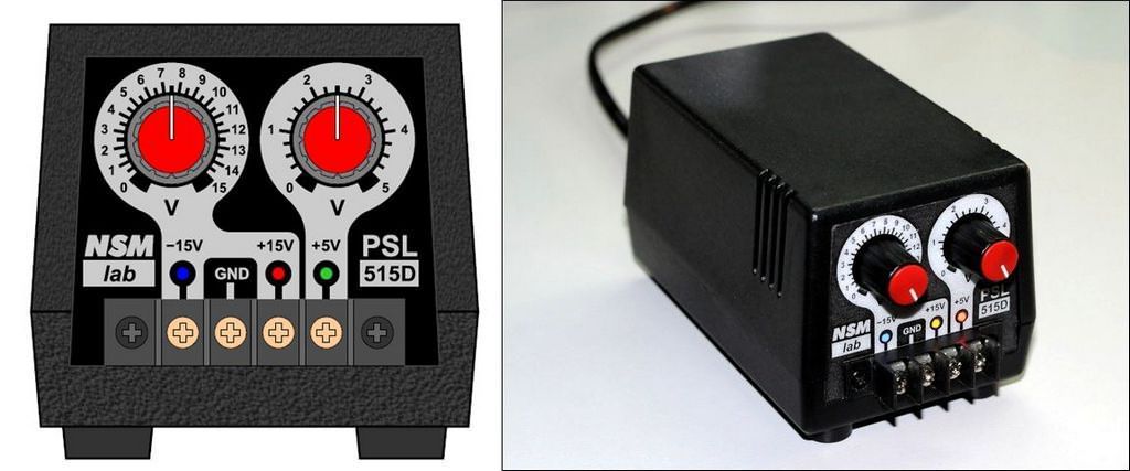
It is a three-output laboratory power supply developed for symmetrical and low-voltage circuits. (LM317, LM337, Opamp, Transistor based)
Technical Specifications
- Output voltages: 0…±15 V and 0…5 V
- Maximum output current: 1 A (Total power is limited to 15 W)
- Power supply: 220 V AC ±%10, 50 Hz
The device has three separate output channels. Two channels operate together to provide an adjustable symmetrical ±15 V output. The third channel can be adjusted independently between 0…5 V.
All channels use the common chassis line. The power supply is designed based on LM317 and LM337 integrated regulators.
Thanks to the circuit structure, voltage balance is maintained at the symmetrical outputs, and the adjustment can be reduced down to the 0 V level.
There is an LED indicator for each channel; the LED brightness varies depending on the adjusted output voltage.
A special supervisor circuit is used to prevent sudden voltage pulses that may occur during power-on and power-off moments.
High-Current Laboratory Power Supply
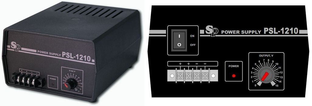
It is a powerful and efficient laboratory-type power supply designed for applications requiring high current. (L4970A, Opamp based)
Technical Specifications
- Output voltage: 0…15V
- Maximum load current: 10A
- Maximum output power: 100W
- Short-circuit protection: Available
- Power supply: 220 V AC ±%10, 50Hz
- Dimensions: 150 × 90 × 200mm
It is suitable for powering stepper motor drivers, high-power control boards, and similar systems. It can be used safely in education, R&D, maintenance-repair, and industrial use scenarios.
The device is built on an integrated switching (SMPS) regulator architecture and provides high efficiency at all output voltages. In the standard model, the output voltage can be adjusted between 0…15 V; different voltage ranges can also be produced.
Voltage adjustment is made with the potentiometer on the front panel. If desired, this potentiometer can be implemented as a trimpot adjustable with a screwdriver. This option is suitable for applications that require fixed voltage and where unauthorized intervention is not desired.
The maximum output current is 10 A, and under continuous operating conditions, the current limit is determined by the load power (100 W). The device has both short-circuit and overtemperature protection.
On the front panel: load terminals, power LED, and voltage adjustment knob
On the rear panel: mains cable, power switch, and ground terminal are located.
0–100 V / 0–100 mA Laboratory Power Supply


A laboratory power supply with unusual parameters such as a 0–100V voltage and 0–100mA current range. The developed power supply is designed for use in applications such as testing LED diodes and measuring the reverse breakdown voltages and characteristics of Zener diodes whose technical data are unknown.
TLC272 type operational amplifiers are used in the regulation circuit. These ICs do not require a symmetrical power supply and can operate in the 4–16 V range.
Since the operating points and saturation levels depend on the supply voltage, the supply voltage of the control circuit was selected as 12 V.
The source operates with a linear operating principle, and the output stage includes a power unipolar transistor driven by a controlled bipolar transistor.
The output stage is controlled by a closed-loop regulation structure that includes two PI regulators, a differential amplifier, and an adjustable current limiter.
The regulators are arranged in a cascade structure, and the voltage regulator operates as the upper-level (master) for the current regulator.
The power supply is powered through two separate transformers. One of them supplies the power stage, and the other supplies the control circuits. All components are placed inside an enclosure that includes a digital display measurement module capable of showing the output voltage and current.
WARNING Be careful when building and testing high-voltage power supplies. Pay attention to capacitor connections. If you connect the + – poles in reverse, large explosions may occur at high voltage. Before operating the circuit, use a fused power line and protective goggles.
Source: leoniv.diod.club/index.html


