
Relay Transformer Mains Voltage Stabilizers Voltage Regulator
Circuits designed for different types of mains voltage regulator stabilizers, especially relay–transformer-based solutions. There are threshold detector circuits used to control the relays and their practical applications. Large transformers are not required for high powers. There is a large archive of 220v voltage regulators from 2 stages up to 8 stages. The system can be considered the same as the relay bypass circuit for adjustable power supplies shared in the past.
Content
- Electronic Stabilizer with IRF840 (not recommended for high powers; after the problems of this system, the relay-based system was adopted)
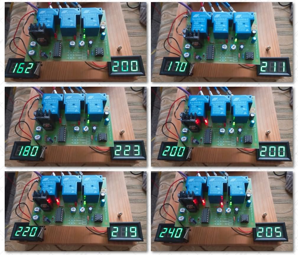
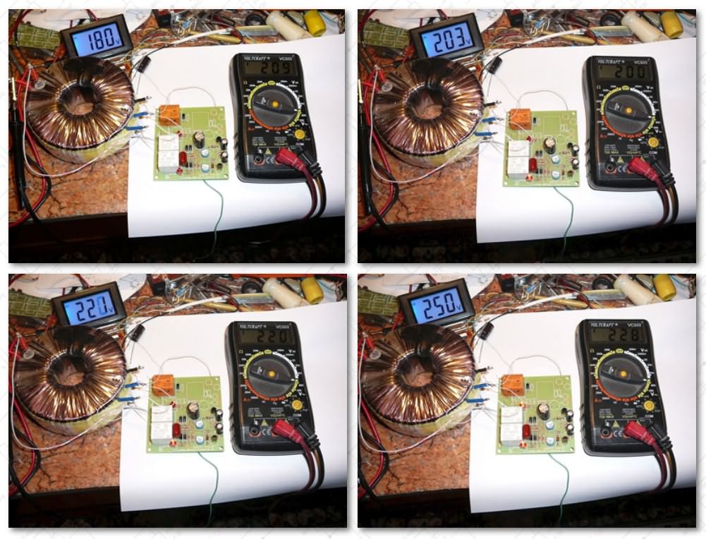
- Relay–Transformer Voltage Regulator Stabilizer
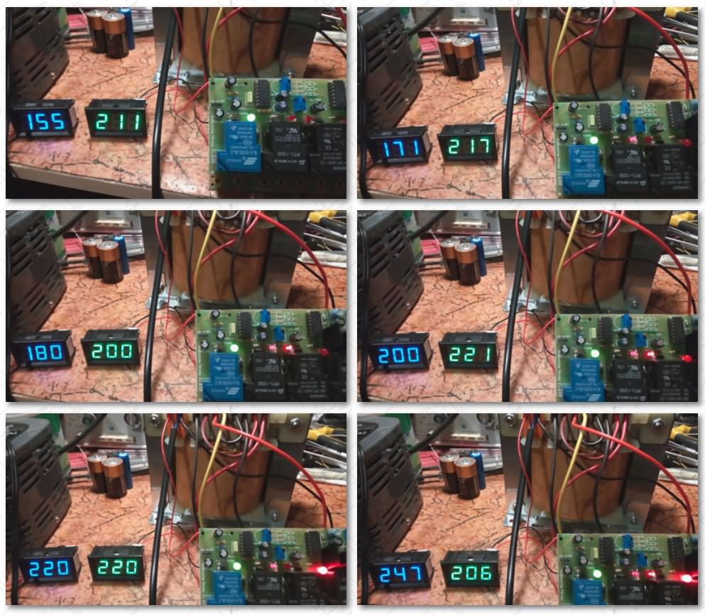
- Relay–Transformer Stabilizer – 2
- Relay–Transformer Stabilizer – 1200 W
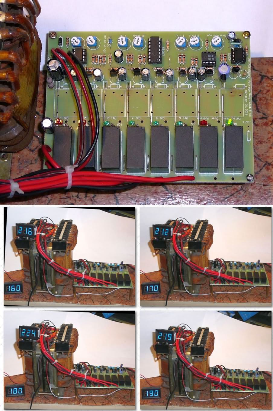
- Relay–Transformer Voltage Regulator Stabilizer – 2000 W
Regardless of the stabilizer type, the common and indispensable element of all these systems is the transformer. Of course, different circuit approaches are also available; however, in this work, solutions that can be implemented in a home environment and under amateur laboratory conditions have been taken as the basis.
Stabilization Based on the Volt-Add Principle
Contents
From an implementation point of view, the easiest solutions to realize are electronic stabilizers.
These are generally not high-power; however, they have a notable advantage:
The load power can be 4–7 times higher than the rated power of the transformer used.
For example, with a 250 W transformer, an electronic stabilizer capable of supplying a load in the 800–1500 W range can be designed.
How is this possible?
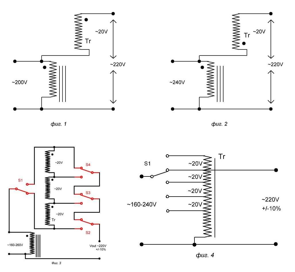
The basic principle is to add voltage by connecting the low-voltage, high-current secondary winding of the transformer in series with the primary winding.
If the secondary winding is connected in phase with the primary, it is added to the mains voltage (boost).
If it is connected in reverse phase, it is subtracted from the mains voltage (buck).
This method is called the volt-add principle.
What needs to be done after this point is to control this connection electronically.
The simplest approach is to build a system that operates only as a booster without changing the direction of the secondary winding. This is because, in practice, the most common problem is a drop in the mains voltage.
For example, while the input voltage varies between 150–200 V, the target is to keep the output within the 220 V ± %10 (200–240 V) range.
Boost and Buck Operating Logic
When the primary and secondary windings are connected in series:
A mains voltage that has dropped to 200 V can be increased to 220 V with a 20 V secondary voltage.
If the same windings are connected in reverse, the mains voltage is reduced by 20 V.
This structure essentially behaves like an auto-transformer.
However, a real mains stabilizer must be able to operate in both boost and buck modes.
The most practical way to achieve this is to swap the secondary winding terminals using electronically controlled relays.
This approach leads us to the concept of relay–transformer stabilizers.
Step Voltage Regulation
If the transformer has multiple secondary windings and these are selected by relays:
10 V
20 V
or step voltage regulation at any other desired value can be performed.
In this way, for example, a system that operates in the 150–260 V range and keeps the output at 220 V ±10 V accuracy can be obtained. This ±%5 accuracy is more than sufficient for household devices.
Of course, one of the relays must be used to change the direction of the secondary winding.
In homemade systems, considering that most electrical devices are already designed to operate within the 220 V ±%10 range, a 20 V step interval is generally sufficient. Step selection is not standard; it depends entirely on the designer’s preference.
In some circuits, unusual values such as 14 V, 15 V, and 17 V can be seen. The reason for this is the desire to apply a large voltage addition during large voltage drops and to make finer adjustments for small deviations.
Power – Transformer Relationship
One of the most interesting aspects of this method is that the load power can be much higher than the transformer power.
For example:
Secondary winding: 20 V
Mains voltage: 200 V
The ratio becomes ≈ 11:1.
In this case: with a 200 W transformer, a load of approximately 2 kW can be supplied.
However, the point to pay attention to is that the secondary winding must be designed to carry this current (for example, 10 A).
As the mains voltage drops, this ratio also decreases.
At a 160 V input, if a 60 V voltage addition is required, the ratio becomes 3.5:1 and the load power is limited to approximately 800 W.
Auto-Transformer and Control Methods
The operating principle of this structure is quite close to the logic of a classic Variac (LATR). The difference is that:
In a Variac, the ratio is changed mechanically,
In relay stabilizers, the windings are switched.
Relays are generally controlled by comparator circuits. This is the simplest and most reliable method for amateur applications. In commercial products, microcontrollers are mostly used.
Frankly, the trend of controlling every device with a microprocessor does not personally seem very appealing; however, the industry is moving in this direction.
Electronic–Mechanical Stabilizers
Another approach is electronic–mechanical stabilizers with servo motors. In these systems:
The output voltage is continuously monitored,
The electronic control circuit drives the servo motor and automatically adjusts the Variac position.
This topic has been discussed in detail in a separate article.
Electronic Stabilizer with IRF840
The starting point of this work was the repeated failure of my refrigerator stabilizer. After being repaired over and over, it had almost no intact part left.
A capacity of approximately 600 VA is practically sufficient for a refrigerator that draws around 300 W of power. This is because when the mains voltage drops to 155 V, the active power drawn by the refrigerator also drops by approximately half.
In the circuit, the output voltage is taken from the other secondary winding of the transformer, rectified, and adjusted with the TL431 reference element. The adjustment is made through the R5 trimpot.
However, due to an oversight here, the incorrect connection of the secondary windings caused the IRF840 to burn dramatically. The photos are the clearest proof of this mistake.
Why Was the Relay Method Adopted?
The main factor limiting the output power in the electronic stabilizer was the power rating of the MOSFET. In the relay method, however, the load is applied directly to the transformer windings, and semiconductors do not become the limiting factor.
Of course, arcing may occur at the relay contacts; however, this problem can be eliminated with a suitable arc-suppression (snubber) circuit.
For this reason, relay–transformer stabilizers are the most widely used solutions in household applications up to 4–5 kW.
The PCB layouts of the voltage stabilizer circuits were prepared with Protel 99 Se. Since there are few Protel 99 Se users and it does not work on new operating systems, I added the Gerber outputs and the .lay6 PCB files obtained using the Sprint Layout 6 Gerber import method.
source: kn34pc.com/construct/v_terziev_st_mr.html


