Sometimes this type of power converter circuits is getting a much needed low-profile single-supply circuitry divides symmetrically fed through the circuit can run.
LM741 op-amp voltage follower 741 is used as the circuit with 18 resistance opamp output voltage is taken from the referents by the formation of the symmetrical voltage is converted into 0-end circuit has been tested by me.
Note: opamp is used to supply the voltage to split you will use the integrated power supply voltage according to the value of the voltage min max input voltage, use appropriate
This is just a kind of accessory that turns your unbalanced sources symmetrical. However, only into small output, mainly to supply backrest and similar low-end applications failing to hand full symmetric source.
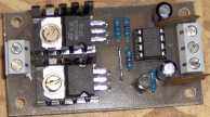
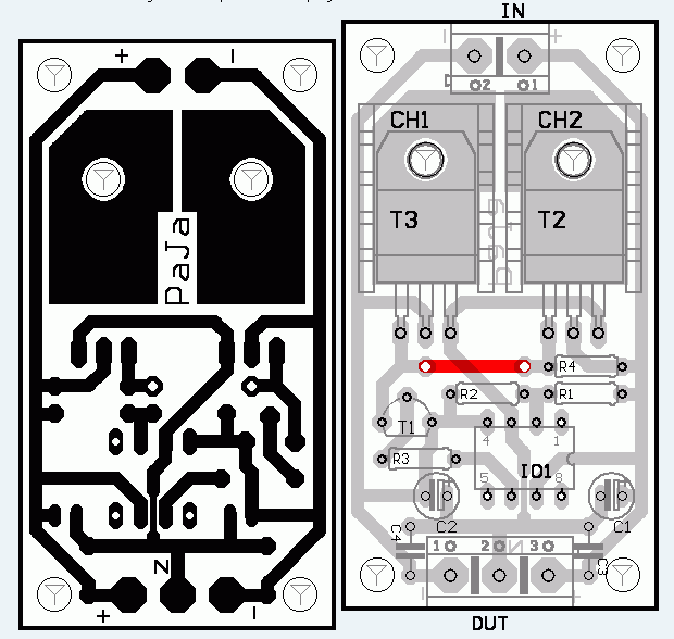
Complete instructions came in A-Radio – Kit and structures 5/2001. The principle activity was simple. Applied voltage parts (halves) resistor divider R1 and R2. To avoid thus formed middle voltage soft and is connected operational amplifier IC1 via the T1 gives complementary pair of terminal transistors T2 and T3. If the consumption of output symmetrical and runs through end transistors minimum current, therefore requiring little cooler. In the original circuit is T1 BC546. I for sure used a BC639 (needed to amend the proposal DPS).
Symmetrical Single Source Supply all files:


Billiards Counters 0-99 Digital Counter Circuit
Billiards Counter Circuit Application circuit and a counter circuit with detailed information on the project uygulanmasa very valuable information. Thanks to those who contributed to preparing
Billiard halls, billiard playing, use the counter to write their numbers. Old type counters, mechanical counters display cartons were turned by hand. Nowadays, electronic counters have replaced them. TTL integrated circuits made of electronic billiards counters are used. Circuit is designed as a two-digit. 3 or 4 can be removed if desired number of digits. Counter the forward / backward counters (74192) Go over to the use of numbers missing or corrected immediately. Code 7447 is used as a solvent.
Manchmal bekommt diese Art von Stromrichterschaltungen eine dringend benötigte Low-Profile-Single-Supply-Schaltung, die symmetrisch durch die Schaltung gespeist werden kann.
Der LM741-Operationsverstärkerspannungsfolger 741 wird verwendet, da der Stromkreis mit 18 Widerstandsampere der Ausgangsspannung entnommen wird, indem die Bildung der symmetrischen Spannung in einen 0-End-Stromkreis umgewandelt wird, der von mir getestet wurde.
Hinweis: opamp wird verwendet, um die Spannung aufzuteilen. Sie verwenden die integrierte Versorgungsspannung entsprechend dem Wert der Spannung min max Eingangsspannung. Verwenden Sie die entsprechende Spannung
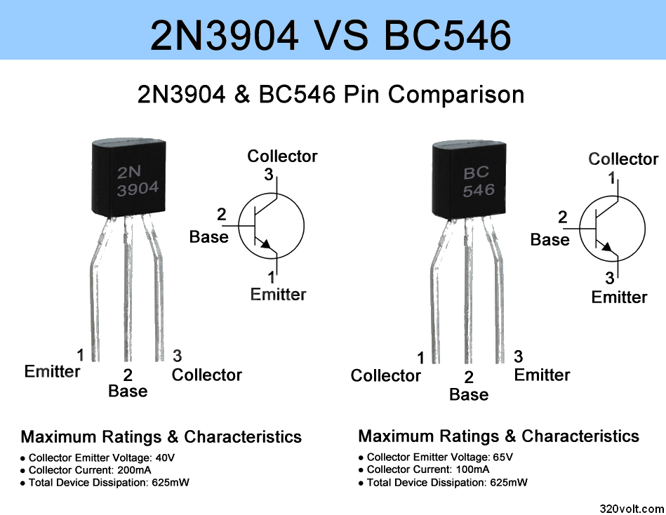
The circuit doesn’t work at all. I used 2N3904 instead of BC546 which is obsoleted. Any advice?
Hi, 2N3904 and BC546 pin connections are different
2N3904 VS BC546 Pin Difference
Hi,
I am trying to build this circuit, but it seems not working.
IC1 = u741
T1 = 3904
R3 = 100 ohm
Did we test the circuit? Any advice for my circuit that doesn’t work? Thanks!
Sincerely,
Mike
@mike the circuit is working i made and i am using it