The automatic battery charger circuit with IRF9540 MOSFET charges 12 V lead-acid vehicle batteries with a transformer rectifier and cuts off the main current at approximately 16 V. Since it consists of simple parts, it is suitable for those who want to build a classic, adjustable, and monitorable battery charger in a hobby workshop or on a service bench.
Operating Principle of the Circuit
Contents
- 1 Operating Principle of the Circuit
- 2 Power Supply and Rectifier Stage
- 3 Cutting Off the Charging Current with MOSFET
- 4 Schmitt Trigger and Automatic Cutoff
- 5 How Does the Battery Charging Process Progress?
- 6 Important Parts in the Schematic
- 7 Points to Pay Attention to During Assembly
- 8 Adjustment and First Test
- 9 Safety Warnings
- 10 Common Mistakes
- 11 Technical Summary
The circuit completes the classic transformer rectifier structure with a charging line switched by MOSFET and a two-transistor Schmitt trigger. When the battery is discharged, the IRF9540 P-channel MOSFET is conducting and the rectified voltage goes to the battery through R8. When the battery voltage reaches the adjusted level, the control stage consisting of T2-T3 transistors turns off the MOSFET.
After the main charging is cut off, the battery is not completely disconnected from the circuit. A small maintenance current flows through R1. This current is selected to be kept around approximately 40 mA. Thus, at the end of charging, the circuit switches to a low-current standby state without forcing the battery with high current.
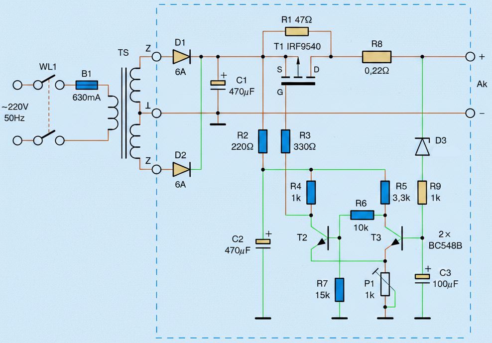
Automatic battery charger circuit schematic with IRF9540 MOSFET
Power Supply and Rectifier Stage
On the mains side, there is the WŁ1 switch and B1 fuse. Since the transformer provides galvanic isolation between the mains and battery side, it is the most critical safety component of the circuit.
The center-tapped symmetrical secondary winding of the TS transformer in the schematic is used as a two-diode full-wave rectifier with D1 and D2 diodes.
The C1 capacitor filters the rectified line. When the battery is connected, the large filtering task is mostly handled by the battery itself; however, C1 is important so that the electronic control stage does not become unstable when the battery is removed.
For more basic information about transformer selection, the page about transformers is also useful.
Transformer Selection
In the original circuit logic, the target is for the secondary voltage to be at least around 2×14 V with no load.
Under load, in the condition corresponding to approximately half of the charging current, the voltage may drop to around 2×11 V.
For batteries up to around 45 Ah, a minimum transformer power of 50 VA is specified.
If a transformer with a single secondary winding is used, a four-diode bridge rectifier is required instead of the two-diode center-tapped rectifier in the schematic.
In such a modification, diode current, cooling, and output voltage must be checked again.
Cutting Off the Charging Current with MOSFET
The IRF9540 used as T1 is a P-channel power MOSFET. Its source terminal is connected to the rectified positive line, and its drain terminal is connected to the battery positive output through R8.
When the gate voltage is sufficiently negative relative to the source terminal, the MOSFET conducts and the main charging current flows.
When the battery is discharged, the T2 transistor is conducting. The level of a few volts at the T2 collector pulls the T1 gate terminal down.
Since the source terminal remains at a high voltage close to the battery line, the gate-source voltage becomes negative and the IRF9540 turns on. The low-resistance conduction characteristic of the MOSFET provides less heat loss compared to a classic series transistor.
R8 is a low-ohm resistor with a value of 0.22 Ω. It both softens current pulses and can also be used like a shunt to measure the charging current.
The approximate current can be calculated by measuring the voltage across it. For example, if 0.66 V is seen across R8, the charging current is around approximately 3 A.
To compare different uses of MOSFETs in rectification and switching applications, the topic of using MOSFETs instead of a bridge diode can also be examined.
Schmitt Trigger and Automatic Cutoff
The T2 and T3 transistors form a simple Schmitt trigger built with BC548B. The emitters of the two transistors are connected to a common point through the P1 adjustment potentiometer.
P1 is used to adjust the cutoff threshold of the circuit.
D3 is a BZX55 C12 zener diode. Before the battery voltage rises, no meaningful drive voltage occurs at the T3 base. When the battery voltage rises and exceeds the zener threshold, the T3 base begins to be driven.
C3 filters this point and reduces short-term fluctuations from causing false cutoff.
When T3 conducts, T2 turns off. When T2 turns off, the T1 gate level rises and the negative gate-source voltage required for the IRF9540 disappears.
The MOSFET turns off and the main charging current is cut. Thanks to the Schmitt structure, chattering on-off behavior around the threshold is reduced.
How Does the Battery Charging Process Progress?
When an empty or partially discharged 12 V lead-acid battery is connected, the circuit first operates in high-current charging mode.
The charging current depends on the secondary voltage of the transformer, the discharge state of the battery, and the losses across R8.
As a general rule, the charging current is selected around approximately one tenth of the battery capacity. For a 45 Ah battery, the range of 4 A to 4.5 A falls into this class.
As the battery voltage rises, the T3 control line is driven more. If the adjustment point is set correctly, the Schmitt trigger changes state around approximately 16 V and the MOSFET turns off the charging line.
After this, only a low maintenance current goes to the battery through R1.
For the general behavior, capacity, and maintenance topics of lead-acid batteries, the article about batteries and cells makes it easier to understand the practical use of the circuit.
Important Parts in the Schematic
| Reference | Value / Model | Function in the Circuit |
|---|---|---|
| T1 | IRF9540 or IRF9530 | P-channel MOSFET; turns the main charging current on or off. |
| T2, T3 | BC548B | Form the Schmitt trigger control stage. |
| D1, D2 | 1N5402 or 6A4 | Perform full-wave rectification from the center-tapped secondary. |
| D3 | BZX55 C12 | 12 V zener threshold component that senses the battery voltage. |
| R8 | 0.22 Ω / 4 W | Limits charging current pulses and can be used as a current measurement point. |
| R1 | 47 Ω / 0.5 W | Provides low maintenance current after the MOSFET turns off. |
| R2 | 220 Ω | Acts as a current limiter in the supply line of the control stage. |
| R3 | 330 Ω | Resistor that limits transitions on the MOSFET gate line. |
| R4, R9 | 1 kΩ | Provides biasing in the transistor and zener sensing stage. |
| R5 | 3.3 kΩ | Works as the load resistor in the T3 collector line. |
| R6 | 10 kΩ | Part of the feedback and biasing line in the Schmitt trigger. |
| R7 | 15 kΩ | Forms the lower reference path in T2 base biasing. |
| P1 | 1 kΩ | Allows the cutoff voltage to be adjusted. |
| C1, C2 | 470 µF / 25 V | Filter the rectified line and control supply. |
| C3 | 100 µF / 10 V | Filters the T3 sensing point and reduces unstable triggering. |
| B1 | 630 mA / 250 V | Protects the transformer primary side with a fuse. |
Points to Pay Attention to During Assembly
R1 and R8 are resistors that may heat up. Instead of laying them in zero contact with the printed circuit board, it is better to leave them a few millimeters above the board surface.
R8 especially dissipates significant power at high current; at 4 A with a value of 0.22 Ω, approximately 3.5 W of heat is generated. Therefore, a resistor with a low power rating should not be used.
D1 and D2 diodes can be selected in the 3 A class for batteries up to around 45 Ah; for higher capacities, 6 A class diodes and suitable cooling are safer.
A heatsink, even a small one, is required for the T1 MOSFET. If the diodes and MOSFET will be mounted on the same metal surface for larger batteries, insulation washers and bushings must be used.
Adjustment and First Test
The first startup should not be done directly with the battery. First, the control stage should be tested with a low-current adjustable laboratory power supply.
P1 is set to the middle position, 12 V is applied to the C1 line, and the control supply across C2 is measured.
The cutoff point is checked by slowly increasing the adjustable supply between 10 V and 20 V.
The target is for the circuit to cut off the main charging at around approximately 16.2 V.
If the cutoff occurs earlier or later, P1 should be adjusted in very small steps.
If there is no adjustable power supply, only the triggering behavior of the circuit can be checked in a limited way; however, the actual cutoff voltage cannot be adjusted precisely with this method.
In the first real charge, an ammeter and voltmeter must definitely be connected, and it should be observed that the MOSFET turns off at the correct point while the battery voltage rises.
Safety Warnings
The mains side is dangerous. The transformer primary connections, fuse holder, and switch section must be made with double-insulated cable; no point carrying exposed 220/230 V should be left open. If a metal enclosure is used, grounding and insulation arrangements must also be checked.
Lead-acid batteries can release gas during charging. Charging should not be performed in a closed, spark-prone, or unventilated place. If the crocodile clips are connected to the battery in reverse, the MOSFET, diodes, or battery may be damaged. Since reverse polarity protection is not shown separately in the circuit, the connection sequence must be done carefully.
The cutoff level of approximately 16 V can be used for controlled charging in flooded automotive batteries; however, this level may be high for AGM, gel, or sealed lead-acid batteries. It is not a suitable circuit for lithium-ion, LiFePO4, or NiMH batteries.
Common Mistakes
- Selecting the transformer voltage too low: When the battery voltage rises, the charging current drops early and the circuit cannot reach the expected capacity.
- Selecting the power rating of R8 too low: The resistor overheats, its value may drift, or it may darken the board.
- Leaving the MOSFET without a heatsink: Especially in high-current charging, T1 heats up unnecessarily.
- Using the P1 setting without measuring: If the cutoff voltage remains incorrect, the battery may be undercharged or remain under excessive voltage.
- Using the same thresholds with sealed batteries: The manufacturer’s charging voltage should be checked for gel and AGM batteries.
Technical Summary
| Feature | Value / Description |
|---|---|
| Battery type | 12 V lead-acid automotive battery |
| Charging cutoff level | Approximately 16 V, adjusted with P1 |
| Maintenance current | Approximately 40 mA, determined by R1 |
| Power switch | IRF9540 P-channel MOSFET |
| Control structure | Schmitt trigger with BC548B transistors |
| Rectification | Center-tapped transformer and two-diode full-wave rectifier |
| Recommended transformer | At least 2×14 V with no load, approximately 50 VA and above |
| Current monitoring | Can be done by measuring the voltage drop across R8 |
The circuit is an understandable example for building a classic battery charger that performs automatic cutoff without using an integrated charge controller. The most important points are transformer selection, the power rating of R8, MOSFET cooling, and making the P1 adjustment by measurement. If the first trial is done in a controlled way, the circuit becomes a very educational application both for observing the charging process and for learning MOSFET-based cutoff logic.
The PCB drawing of the MOSFET battery charging circuit was copied with Sprint Layout 6. It was checked but not tested. In addition, the original drawings are also included.