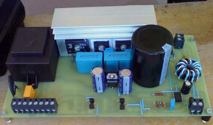
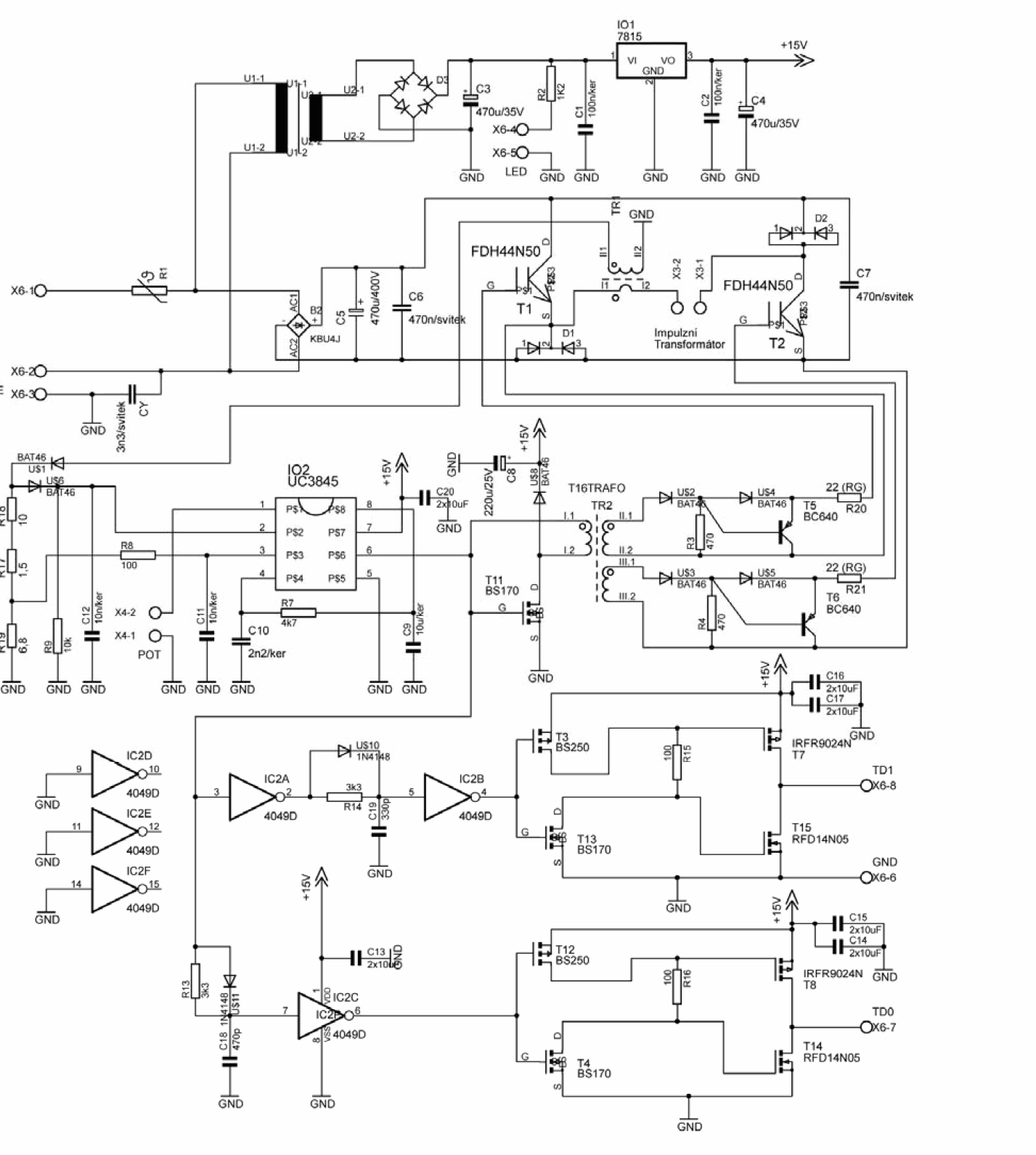
SMPS Soldering Station Circuit However, this voltage is linear increasing tendency due to the existence of the magnetizing current of the main transformer and due to the limited inductance of the inverter output choke. By comparing this actual current flow (pin 3 UC3845) with the setpoint setpoint (pin 1 UC 3845) is directly generated PWM signal and at the same time a current control loop is realized. They are on the primary side Fairchild MOS-FET transistors, type FDH44N50 (44A, 500V, 0.12Ω). As demagnetizing diodes are used by Fairchild’s two-diodes, type ISL9K860 (2x8A, 600V). IN link impulse electrolytic capacitor C2 470 μF / 400V is used.
As close as possible transistors and demagnetizing diodes are still connected in the intermediate circuit Polypropylene non-inductive capacitor C1 470nF / 400V. For the drive control purposes, the primary pulse transformer primary current is scanned current transformer.
In common practice, soldering pliers of similar performance are manufactured using a heating spiral which, heats the copper soldering iron – the tip. Such a solution is relatively simple, it ensures good
heat dissipation to the solder joint. However, it has a number of drawbacks: a large heating time (considerable thermal capacity), usually lack of power regulation capability, large dimensions of the contact soldering surface tools. For these reasons, soldering was solved using a DC / DC converter with a transformer. Using a transformer with a 50 Hz network frequency is not appropriate because of it of considerable size and weight. In the inverter the transformer is smaller, its working frequency is ranges in the order of tens of kHz. This is a source of high current and low voltage.
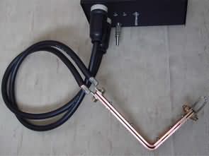
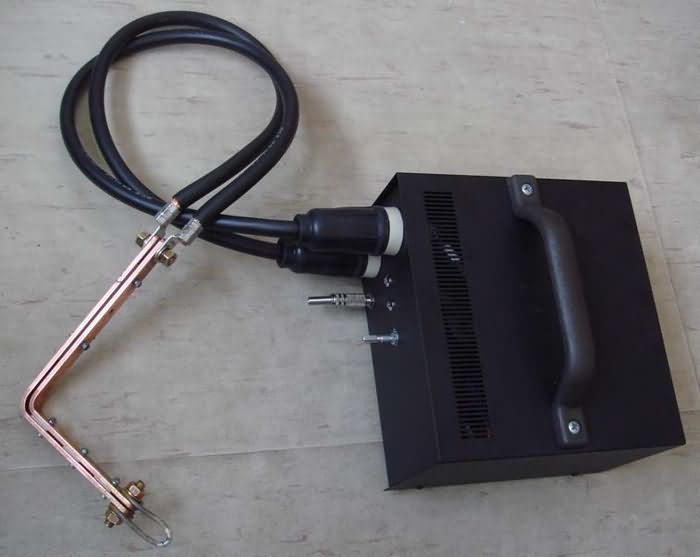
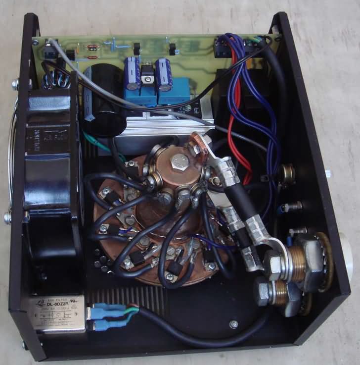
The whole device consists of a source – a soldering station, and an external one connected to it
device – soldering adapter. Uses are for soldering larger volumes, where it is performance of common transformer soldering equipment insufficient – connecting of larger cross-section cables, soldering
sheets.
If, at a high power of 500W, we wanted to re-implement the copper wire (p small resistivity), we would have to produce a larger stitch, but with the length and cross section. The eyelet must not be too long and thin to ensure sufficient heat removal from the whole sockets into the soldered joint.
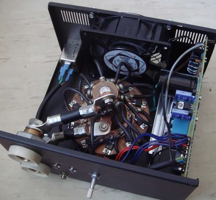
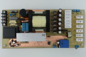
On the secondary side, a rectifier is used instead of rectifying and zero diodes implemented by the MOSFET transistors in order to reduce the losses by conducting a large output current. Instead, 10 pieces of IRF 2804 connected in parallel are used in place of each diode. Channel resistance in the closed state of one transistor is 2mΩ, ie the resulting resistance of 10pcs in parallel is about 0.2mΩ. At passing through the current 510A results in a voltage drop of only about 0.1V while in the passive rectifiers with Schottky diodes would be at least 0.5V. Thus, the described solution we greatly reduce the power loss on the secondary rectifier (minimum 5 times). The synchronous rectifier is for a low output and high current converter standard solution.
![]()
FILE DOWNLOAD LINK LIST (in TXT format): LINKS-26035.zip

Schaltnetzteil Lötstation Schaltung UC3845 500W
Schaltnetzteil SMPS-Lötstationsschaltung Diese Spannung ist jedoch eine linear ansteigende Tendenz aufgrund des Vorhandenseins des Magnetisierungsstroms des Haupttransformators und aufgrund der begrenzten Induktivität der Wechselrichterausgangsdrossel. Durch Vergleich dieses tatsächlichen Stromflusses (Pin 3 UC3845) mit dem Sollwert-Sollwert (Pin 1 UC 3845) wird direkt ein PWM-Signal erzeugt und gleichzeitig ein Stromregelkreis realisiert.
Sie sind auf der primären Seite Fairchild-MOS-FET-Transistoren, Typ FDH44N50 (44A, 500V, 0.12Ω). Als Entmagnetisierungsdioden werden Fairchilds Zwei-Dioden vom Typ ISL9K860 (2x8A, 600V) verwendet. IN-Link-Impuls-Elektrolytkondensator C2 470 μF / 400V wird verwendet. So nahe wie möglich sind noch Transistoren und Entmagnetisierungsdioden im Zwischenkreis angeschlossen. Polypropylen-Nichtinduktiv-Kondensator C1 470nF / 400V. Für die Antriebssteuerungszwecke ist der primäre Primärstrom des Primärtransformators ein abgetasteter Stromtransformator.
Circuit de station de soudage à découpage
Circuit de la station de soudage SMPS Cependant, cette tension est une tendance à l’augmentation linéaire en raison de l’existence du courant de magnétisation du transformateur principal et en raison de l’inductance limitée de l’inductance de sortie de l’onduleur. En comparant ce flux de courant réel (broche 3 UC3845) avec le point de consigne de consigne (broche 1 UC 3845), un signal PWM est généré directement et en même temps une boucle de commande de courant est réalisée. Ils sont du côté primaire des transistors Fairchild MOS-FET, type FDH44N50 (44A, 500V, 0,12Ω). Comme les diodes de démagnétisation sont utilisées par les deux diodes de Fairchild, tapez ISL9K860 (2x8A, 600V). Un condensateur électrolytique à impulsion de liaison IN C2 470 μF / 400V est utilisé.
Des transistors et des diodes de démagnétisation aussi proches que possible sont toujours connectés dans le circuit intermédiaire Condensateur non inductif en polypropylène C1 470nF / 400V. Aux fins de contrôle du variateur, le courant primaire du transformateur d’impulsions primaire est un transformateur de courant balayé.