A detailed subwoofer project. Test audio files designed for a 12-inch 400w speaker are shared (in .wav format). Parametric equalizer active filter is a quality design.
Boost-Cut, Frequency, Q, X over, Phase, Volume settings can be adjusted. When you listen to the test sounds, you will clearly understand what the equalizer and filter circuit can do. There are very deep bass sounds, detailed measurement graphics have been added and tests have been made at various frequencies.
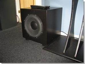
Unique 12 XLS-based Subwoofer
A subwoofer project. The project actually started a few years ago and was designed for my home theater system. It ended up being a sub for my stereo speakers. It took some time to build both the preamp and the power amp, and in the meantime I started setting up my home theater system, which took quite a bit of time.
When I say this is for my HT and ends up being my stereo’s subwoofer, it’s because I’ve gotten my hands on some THX certified JBL subwoofers (HT1) and contrary to what many people will tell you, it’s really tough. just building a good subwoofer with very large vents, especially for an HT, as you won’t have a problem when it goes down to something like 40 Hz. On the other hand, JBL submarines are really big. 2 times 120 liters!!!!
If you don’t have room for such big monsters, then a closed box design with a large amp is the best way to go. That’s what this project is about. The build is based on Peerless’ renowned 12-inch XLS woofer. This is a really good subwoofer driver, with some very good little parameters, a reasonable long pass and good power handling. It is specially produced for such structures.
Without a passive driver which might be another good option, it needs some balancing for real bass playback. You will need 11 db on the selected box to flatten it to 25 Hz. With the 400 W the class D amp will provide, you’ll have about 99 db at 25 Hz, which I think is a respectable value.
In contrast, my two JBLs will produce about 108 db! so i chose these for HT. On the other hand, there is no doubt that the XLS will sound better by going deeper. So it is more suitable for my stereo setup.
result, sound
The main speakers don’t shy away from bass and go pretty deep. They use two-port 8-inch woofers each, again from Peerless, and go down to about 30 Hz. Not much music stuff goes below 30Hz, but very few really make the experience more physical, giving a sense of weight and a better sense of space.
Subwoofer Equalizer Project

The input consists of an inverted pickup amplifier that also includes a 1st order low pass filter that cuts at 1 kHz. The input is designed to accept both high level signals from one or two speaker terminals or one or two line level terminals. The most common use would be in a 5.1 system where it is powered from the dedicated LFE channel, but it can easily be used to assist in a dedicated stereo system.
high pass filter
The next stage is a 4th order high pass filter whose sole purpose is to shield the speaker from low frequencies. Using a large amplifier can easily exceed the mechanical bias limit and damage the driver.
Bass Boost
The reinforcement part is done by a Linkwitz Transform. This is an almost magical circuit that lowers the resonant frequency to any desired level and sets an arbitrary Q system. This section includes two of these circuits because it may be desirable to change the lower frequency limit to adjust the overall frequency. room response At the lowest frequencies, the room will actually boost the bass as the wavelength becomes larger than the room size.
The ascent normally starts at about 30 Hz and rises by 12 dB/octave (order 2). This is the same rolloff characteristics as the Linkwitz Transform, just of the opposite sign, and so it would make sense to aim your Fs for 30 Hz, which should theoretically give a flat room reverb.
After some experimentation I chose an fs of 25 Hz and Q=0.5 which stands for critical damping. I also decided to use this subwoofer for stereo only (as I got myself two JBL 12″ units in large ported boxes for movie they don’t get that low, probably a lot more distortion, but man can they get some air 🙂
Phase Correction
To get a flat echo around the crossover frequency, you need to adjust the phase. The circuit will be able to adjust the phase between 0 and 180 degrees at 80 Hz.
80 Hz is the normal crossover frequency for a surround system, but you may want to use a different crossover to get a smoother transition to the main speakers. That’s fine, but in this case it won’t be able to set the phase exactly 180 degrees.
In practice, you should play an 80 Hz tone and adjust the phase until you get the maximum output.
low pass filter
The low pass filter is for switching to main speakers or satellites and can be adjusted between 30 and 160 Hz.
I chose a quadratic filter as it would match a closed box rolling property. If you are using the circuit with a ventilated system, turn off the vent (wrap a few socks and tuck them into the port/vent), this will give you a sealed box instead.
source sensibleaudio.dk/SubZero/SubZero.htm Subwoofer Project with Parametric Equalizer files


Computer-Controlled Programmable RGB LED Driver PIC16F628 PWM
An interesting project computer-aided olmasıda a very good feature. Supervision can be said that the RGB PWM circuit PIC16F628 dali assembly prepared with software installed on the RGB data while sending the program’s visual basic code through a source-based communication used in section MAX232 RS232 serial port data is sent from the pic PIC16F628
We are going to control RGB LED with a microcontroller. Using Pulse Width Modulation (English: Pulse Width Modulation or PWM), we can digitally analog signal opwekken.Ik have used a software PWM. This is thus applicable to PIC’s with and without hardware PWM. The LEDs are connected directly to the pic outputs without ballast resistors. This is possible because the outputs are limited to a maximum of 25mA internally.