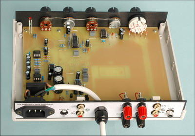
A multi-purpose control circuit Low pass, High pass, Filter stages between 30..200khz Parametric equalizer stage There are frequency, level, boost controls, and there is also an electronic switch circuit that cuts the isolated amplifier from the mains supply with the SSR SY-4089 (Solid State Relay) circuit. .
Subwoofer Controller
Adding a subwoofer to your home theater or hifi system is the easiest way to get deep bass. A relatively small speaker system powered by a large amplifier can deliver bass sounds without taking up too much space. This new Subwoofer Controller has all the features you want, including low and high pass filters, parametric equalizer and auto-on.
Adding a subwoofer to a home theater or hifi system can expand the system’s response towards low bass frequencies, providing a dramatic improvement in listening pleasure. However, this development can be fully realized if several basic conditions are met:
1. The crossover between your main speakers and subwoofer is smooth, with no noticeable peaks or drops in overall frequency response during crossover; Otherwise the system will sound bass or boomy or weak.
2. The subwoofer level is correctly balanced or matched with the level from the rest of the system speakers.
3. The response of the subwoofer itself is smooth throughout its operating frequency range (ie, with no obvious peaks or dips).
4. Very low (subsonic) frequencies are prevented from reaching the subwoofer; because they can cause the cone to ‘flip around’ – this can cause unwanted noise and possible damage to the subwoofer.
The Subwoofer Controller unit we describe here caters to all these conditions.
Appropriate adjustment of the subwoofer high-frequency rolloff allows you to achieve the smoothest transition possible.
Easy adjustment of subwoofer level for optimum overall tonal balance.
A parametric equalizer circuit that allows you to compensate for any response peaks or dips that may be in the operating range of the subwoofer to achieve a smoother response.
There’s also a built-in subsonic high pass filter that steeply rounds the response below 15Hz to protect the subwoofer from damage.
Subwoofer Controller Features
- Input impedance: Line level and LFE signal inputs 47kΩ
- Loudspeaker line, 10kΩ inputs with 11:1 mixing split
- Gain: -8dB to +8dB, variable
- Low pass filter: corner frequency variable between 41Hz and 200Hz
- 12dB/octave swing slope
- Parametric equalizer: Center frequency variable between 30Hz and 200Hz
- Cutoff/boost variable between ±12dB at center frequency
- High pass (subsonic) filter: Corner frequency 15Hz, return slope -18dB / octave
- Signal-to-noise ratio: -80dB unweighted based on 1V RMS input,
- 2V RMS output Maximum output signal: 2.4V RMS
- Output impedance: 1kΩ (both outputs)
- Amplifier standby time: About 11 minutes after the end of the signals
- Power Requirements:. It operates from 12V DC, a battery or regulated plug pack supply.
- Current consumption is less than 45mA in standby mode, less than 60mA in active mode.
Three signal sources
In addition, there is the possibility to choose from three possible sources for the subwoofer signal: line-level outputs from your main amplifier; Speaker level outputs or ‘LFE’ (low frequency effects) channel output from your DVD player or surround sound decoder; There are normal and reverse subwoofer output signals at the end, so you can easily use a stereo amp to drive the subwoofer in bridge mode.
It also has an auto-on circuit to automatically turn on your subwoofer’s amplifier as soon as it detects the presence of audio signals. It then keeps the amplifier powered on while the audio signals are fed into the controller and turns it off again after waiting for about 11-12 minutes only because they are no longer detected.
So you no longer have to worry about remembering to turn the power to the subwoofer amplifier on or then turn it off again.
All circuits of the controller are compact, and operate from a single 12V DC supply from either a battery or a regulated electrical outlet.
How does it work?
Subwoofer Control Project

As you can see in the block diagram, the source selection switch is located at the inputs, allowing you to select between the left and right channel line outputs of your main amplifier, the speaker outputs, if any, or the LFE of your surround sound decoder or DVD player.
The line and speaker level stereo inputs are each mixed together to produce a mono signal for the Subwoofer Controller, but since the LFE signal is already mono, no mixing is required.
Signals are selected with the S1 knob, then go through an input buffer stage that lets you adjust their level (and therefore subwoofer volume) for tonal stabilization.
The input buffer uses a feedback type level control that can either decrease or increase by up to 8dB and offers a 16dB adjustment range that is more than adequate.
The signals then pass to the low-pass filter stage, which can be adjusted between 41Hz and 200Hz. This allows you to “fine-tune” the crossover frequency that the subwoofer takes over from the main system speakers to provide the smoothest transition.
(This filter is not needed when using the LFE signal to drive the subwoofer, so set the low-pass filter to set its frequency to the lowest.)
The next step is the parametric equalizer stage, which allows you to compensate for any peaks or dips (lows) in the subwoofer’s own frequency peak. It does this by allowing you to create a counter trough or peak at any frequency in the 30Hz to 200Hz range and with an amplitude of up to 12dB either way.
This should smooth out any potential peaks or drops in the subwoofer’s performance, provided it is in a reasonably damped environment.

Source: http://www.siliconchip.com.au/cms/A_109076/article.html
Subwoofer Control Circuit PCB schematic alternative link:


Simple Cheap PIC and dsPIC Programmer Circuit
PIC, dsPIC Programmer circuit DSPIC PIC30F series and other classic pic microcontroller can program the software used Wi Pic Programmer PC connection serial port (RS232) max supply voltage of 16 volts DC
PIC dsPIC Programmer