This circuit controls the water level of water tanks or wells. Three level probes are used in the tank to measure the water level. These are conductive rods with a plastic sheath. Probe A determines the top level of water. The B probe determines the level at which the water will be the lowest. The C probe is the probe to be connected to the bottom of the tank or to the outer chassis if the tank is metal.
Its job is to introduce some electric current into the water. This current triggers the transistors connected to other probes. The optocouplers connected to these transistors send logic commands to the PIC pins.
The purpose of using optocouplers (4N25) is to prevent the PIC from breaking down when there is a high voltage electrical leakage for any reason in the water in the tank.
When you run the circuit for the first time, the PIC checks the A and B probes in turn, and if one of them is empty, it immediately starts the tank filling engine. The switch connected to the GP3 pin of the PIC controls the water pump motor.
Pump motor does not work during tank filling. When the water level reaches the A probe, the filling motor stops and you can now use the pump motor with the switch connected to the GP3. If the water level drops below the B probe while pumping the water, the pump motor will stop and the tank filling motor will start until it reaches the A probe.
If the water filling process does not take place, that is, if the water level does not reach the B probe within 1 minute when the tank filling engine starts for the first time, the water filling engine will automatically stop and the ERROR LED will start to light.
From this moment on, the pump and filling motors will not start until the water level reaches B. The ON–OFF switch can also be used to reset the circuit.
You can also optionally remove any of the motors in the circuit. For example, if you are going to use the circuit in a well, you can only connect the pump motor, since there is no water filling process here. In this way, when the water level in the well drops below B, the pump motor stops and does not work until the water level rises to A again. When the water runs out and fills up again, the pump will not start again even if the motor is on. the engine must be turned off and on again with the key.
The A’ and B’ leds show the status of the A and B probes.
PIC software is prepared with proton basic. In addition, PBP version of the software and PIC12F629, PIC12F675 versions are also available upon request.
Printed circuits and proteus 7.5 sp3 simulations are also available in the source files. If the proteus version you are using does not comply with this, import the “isis section” and “ARES region” files in the folder and save them as different.
CIRCUIT TESTED.
Note: we help those who want changes to the software. The circuit is designed for educational purposes.
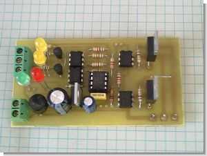
Completed water level control circuit diagram and printed circuit pcb images
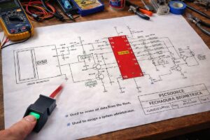
Water Level Control Project Schematic


PIC12F629 Water Level Control Circuit Proton Basic Project files ( isis, ares, pic-basic, proton ) and the materials used in the circuit datasheet files:


LM1875 22W Stereo Amplifier Circuit Tone Controlled
A lot 5.1 sound system used in the quality of an amplifier IC lm1875 circuit two used this integrated shape and leg connections TDA2030A is the same amp for the supply rectifier and filter capacitor the same pcb on the tone control (bass, treble) for what 5532 op-amp used in addition to called bypass feature has low noise opamp amplifies the tone 15volt zeners achieved by the supply the circuit is working with symmetrical voltage transformer to be used must be 2x2amp 2x18v
Tone Controlled LM1875 Stereo Amplifier