In order to test the electrical resistance of insulators, it is necessary to have a voltage source. The required output voltage depends on the type of materials tested. In this case, it is a source of adjustable output voltage in the range of 50V to 2kV sine wave with a frequency of 50Hz. The power supply should be short-circuit proof (protection of the power supply in case of breakdown of the test insulator sample) and the maximum current should be limited to a level to avoid electric shock, but the test sample capacity should not cause current limitation.
This value cannot be determined yet, as it depends on the size of the electrodes attached, the permittivity of the test sample and its thickness. We will work with 15mA. The source will be set up using a PC via USB. The actual (measured) current and voltage values will be sent to this control computer. For safety reasons, the output voltage must be galvanically isolated from the mains voltage.
The ‘isolation’ can be linked to many areas of human activity. For example, it may be thermal insulation that reduces heating losses or prevents unwanted condensation. In this case, the insulation is required to have a high thermal resistance, i.e. a low thermal conductivity. In addition, sound insulation intended to prevent sound propagation or penetration, such as motor vehicle insulation, music studio insulation to absorb unwanted reflections, etc.
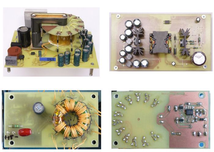
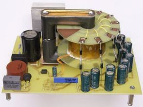
Power supply for floating elements The simplest way is to use an existing DC/DC converter as a component. The price per piece is acceptable and inverters with 3 kV insulation resistance are commonly available. Up to 12 DC/DC converters are likely to be needed in this application. The price is already high for such an amount. Using a DC/DC converter from a supplier is not the only possible solution and in our case it will be more convenient to make a DC/DC converter. One variant is the use of a transformer having one primary winding and 12 secondary windings.
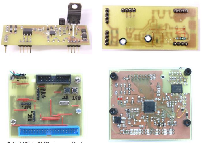
A variety of integrated circuits from various manufacturers are available to control resonant transistor transistors. For simplicity, the ON Semiconductor NCP1392 controller in the SOIC8 package was selected. The advantage is a small housing, the possibility of using two MOSFET type N, undervoltage monitoring and built-in oscillator, which is controlled by current from the Rt pin
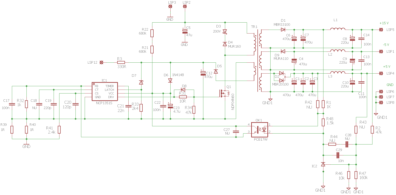
Converter specifications:
Input voltage: 15 V
Output voltage: 12 x 10 V, voltage resistance between windings> 1 kV
Voltage Accuracy: Stabilization is not required
Output current: 12 x 10 mA
Output power: 120 mW
Switching frequency: selected at 100 kHz
According to the literature, the resonant circuit and transformer were designed. Core for transformer is of toroidal type from EPCOS, type B64290L618X27. For the total transferred power, the core is oversized, it was chosen for easier placement of 12 secondary windings with sufficient voltage resistance.
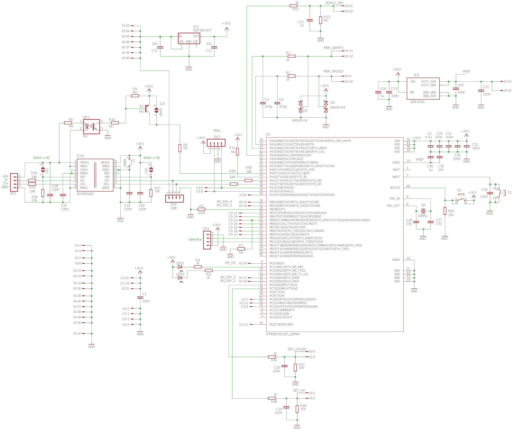
The microprocessor STM32F105 used enables the program update function via USB interface. The advantage of this feature is that no programmer is needed to write to the program memory in the MCU. The program is updated using the Device Firmware Upgrade standard (DFU). This function has been verified and the program can be updated via the used USB separator ADUM3160. To record a program, you must first start DfuSE, then start the program recording mode on the MCU board.
2kv power supply Circuit Schematic
![]()
FILE DOWNLOAD LINK LIST (in TXT format): LINKS-26363.zip


STM32 Alimentation haute tension 50V-2KV NCP1351
Afin de tester la résistance électrique des isolateurs, il est nécessaire de disposer d’une source de tension. La tension de sortie requise dépend du type de matériaux testés. Dans ce cas, il s’agit d’une source de tension de sortie réglable dans la gamme de 50V à 2kV d’onde sinusoïdale avec une fréquence de 50Hz. L’alimentation doit être résistante aux courts-circuits (protection de l’alimentation en cas de panne de l’échantillon d’isolant de test) et le courant maximum doit être limité à un niveau pour éviter les chocs électriques, mais la capacité de l’échantillon de test ne doit pas provoquer de limitation de courant .
Cette valeur ne peut pas encore être déterminée, car elle dépend de la taille des électrodes fixées, de la permittivité de l’échantillon à tester et de son épaisseur. Nous travaillerons avec 15mA. La source sera configurée à l’aide d’un PC via USB. Les valeurs actuelles (mesurées) de courant et de tension seront envoyées à cet ordinateur de commande. Pour des raisons de sécurité, la tension de sortie doit être isolée galvaniquement de la tension secteur.
L’isolement peut être lié à de nombreux domaines de l’activité humaine. Par exemple, il peut s’agir d’une isolation thermique qui réduit les pertes de chaleur ou empêche la condensation indésirable. Dans ce cas, l’isolation doit avoir une résistance thermique élevée, c’est-à-dire une faible conductivité thermique. De plus, une isolation acoustique destinée à empêcher la propagation ou la pénétration du son, telle que l’isolation des véhicules à moteur, l’isolation des studios de musique pour absorber les reflets indésirables, etc.