
The Electronic Bird, Rodent Repeller is a highly effective and environmentally friendly device for repelling birds. With a sound level exceeding 100dB, it can repel not only birds but also small rodents (mice, etc.) from your garden or warehouse. The bird and rodent repeller can be powered by a 12VDC 1-amp adapter or a battery.
Bird Repeller Device Features
Contents
Randomly activated sound signal
Continuously adjustable siren frequency
Internal darkness switch
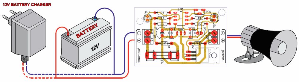
Power supply: 12V/1A (battery or adapter)
PCB Board dimensions: 40x62mm
Rodent Bird Repeller Circuit Description
The ATTINY25 microcontroller-powered bird repellent device is designed to effectively combat bird pests. It is sufficient as basic protection against fruit-eating birds in orchards. Bird repellents emit a very loud, random single-tone sound.
Thanks to the LDR and darkness switch, the audible signal is only heard during the day, and regardless of the selected settings, the user can be sure the repellent will not operate at night. The system must be powered by a 12V battery or a regulated power supply with 12VDC voltage and approximately 1A output current.
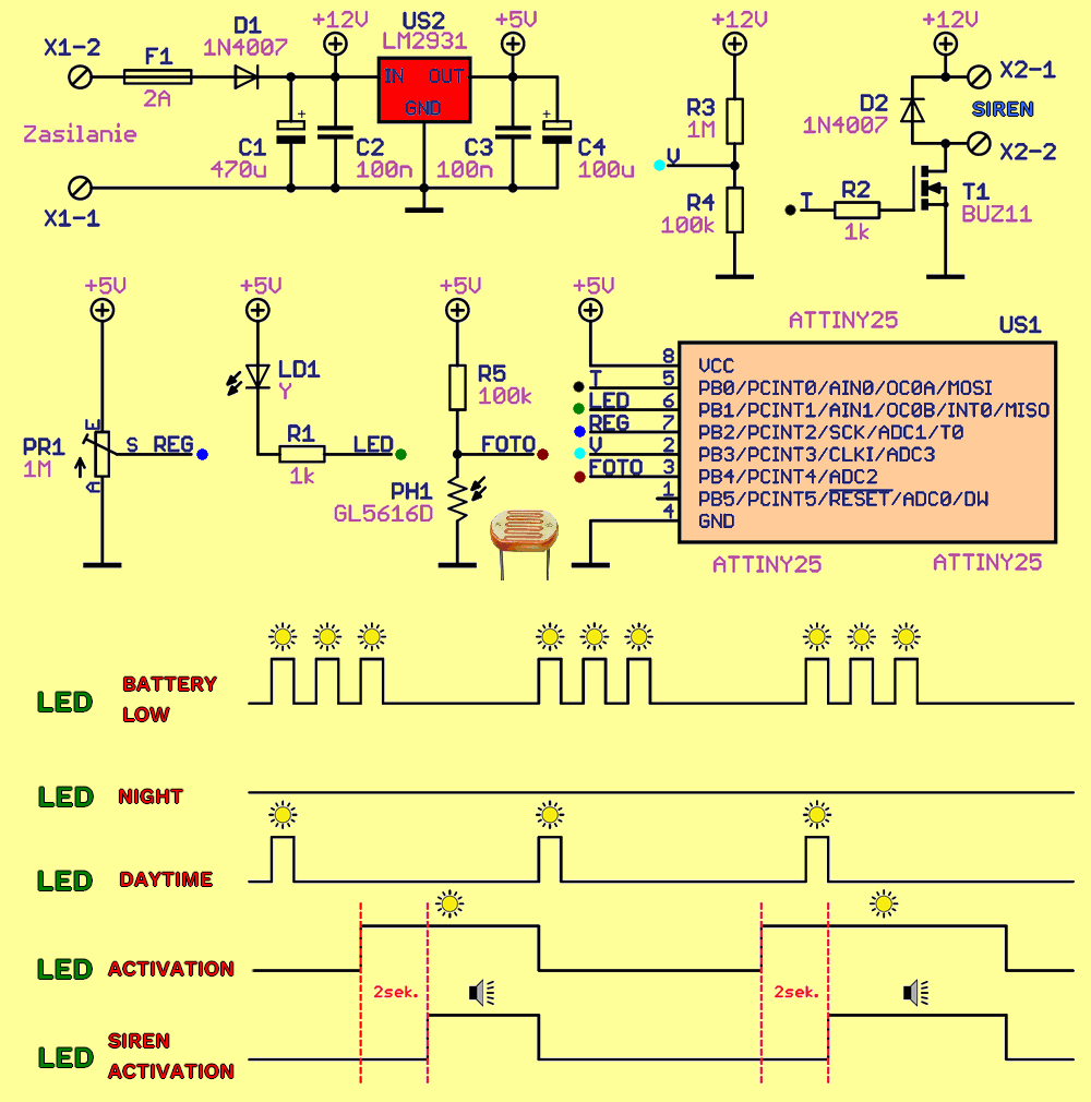
A 1N4007 diode D1, connected in series to the power supply input, protects the system against reverse-polarity voltage input. The 470uF C1 and 100uF C4 capacitors serve as power supply filters. The input voltage from terminal block X1 is reduced to 5V by the LM2931 regulator. The LM2931, an LDO regulator, was selected to reduce current consumption.
The ATtiny25 microcontroller, timed by an internal clock signal without using an external crystal, controls the alarm. A resistive divider consisting of resistors R3 and R4 connected to port PB3 allows the microcontroller program to measure battery voltage without risking damage from overvoltage.
To ensure the system operates only in daylight, a photoresistor LDR GL5616D is used, along with a 100K resistor R5, forming another resistive divider. The voltage signal due to the illumination is sent to port PB4 of the ATTINY25 microcontroller. To simplify operation, the circuit uses only a single control element: potentiometer PR1, which adjusts the siren’s activation frequency. The adjustment period ranges from 5 to 30 minutes.
To ensure the circuit generates random deterrent sounds, the program is written to use the value set by the potentiometer and calculate it along with the photoresistor signal. The program also takes into account the number of signals within the specified time period and the siren duration. This duration can vary from 3 to 8 signals lasting 2 to 5 seconds.
The LED used for the indicator flashes indicates the device status. When the battery is low, three short flashes occur every few seconds. From dusk to dawn, the LD1 LED is off to minimize power consumption. During the day, the LED flashes every few seconds, indicating that the repeller is functioning properly. When the repeller is activated, the LED illuminates, and after 2 seconds, the siren sounds through transistor T1.
Bird Repeller Device Connection Diagram
source: sklep.avt.pl/pl/products/mikroprocesorowy-strach-na-ptaki-kit-avt3135-171448.html source code link


