Especially for microcontroller based projects, you can use the robot’s various sensors, sensing application circuits,’s examples and information
Also prepared with pic16f series circuits and source code through assembly has ams.
SHARP example IS471F light sensor detection circuit
CNY70, LM358 opamp sensor application
GP2DXX distance detection sensor application (PIC16F876, LCD)
74LS14 LDR, light sensing application
LM35 temperature sensing temperature meter circuit (PIC16F876, lm336, LCD)
SHT11 humidity sensor information and application test circuit (pic16f876 LCD)
Robot Projects Examples of Sensor Circuits

INFRARED Reflexive IS471F
Description : Sensor based on the device SHARP IS471F immune to interferences of normal light. This sensor incorporates a modulator/demodulator integrated in its framework and through its side 4 controls a diode LED of infrared external , modulating the sign that this will emit, for to be grasped by the IS471F that contains the receiver. when an object is situated in front of the joint transmitter/receiver splits of the light emitted is reflected and demodulate to activate the exit in the pin 2 that will pass to The sign grasped is sufficiently strong.
The use of light to InfraRed modulated considers object to do al relatively immune sensor to the interferences caused by the normal light of a lightbulb or the light of the sun.
Operation : As can be seen in the plan, the sensor is fed for its ducklings 1 and 3 and these they correspond to Vcc and Gnd respectively, the duckling 2 is the exit of the detector and the duckling 4 is the exit that modulates al led external transmitter. By means of the potentiometer P1 itself various the distance to which is detected the object. Against but drop be the resistance of this potentiometer, but intense will be the light emitted by the diode to GO and therefore greater the distance to which can detect the object.
The the following plan we see the easy necessary circuit to cause to function al sensor.
Uses : I Believe that these they are used for detection of obstacles by reflection and detection of opponents in battles of SUMO. (I say I believe because even not and tested this device and not itself that sensibility has and if is adapted for this)
Ideas and updates : In the previous circuit what we see is a detector of adjustable fixed distance by a potentiometer, but serious possible to do it of several distances or even one gradual detector of distances. For several distances would be able to exchange several resistances and thus to calculate the distance of the object doing tests before, and creating a board of equivalences. For the possible also serious gradual detector controlling the current that arrives him al diode transmitter by means of a converter D/A and a circuit of power based the some transistor, all this controlled by a µController.
Not yet and it tested nothing and this so alone are ideas but if someone tests him and he wants to share his experiences, we would be thanked him all.
Reflexive CNY70
Description : The CNY70 is a small device with form of bucket and four ducklings that lodges in its interior a diode transmitter of infrared that works to a length of wave of 950 nm. and a fototransistor (receiver) being both arranged in parallel and aiming both in the same direction, The distance between transmitter and receiver is of 2.8 mm. and they are separated of the front to the encapsulate for 1 mm.
The the following figure we see the internal disposition of the CNY70 looking at the encapsulado from above, thus therefore we have the diode transmitter of infrared to the left and the fototransistor to the right.
Operation : The fototransistor will conduct but, against but light reflected of the transmitter grasp for its base. The exit of this device is analog and comes determined by the quantity of light reflected, thus therefore to have a digital exit would be able to put a disparador Trigger Schmitt and thus to obtain the digital exit but this has a problem, and the fact is that is not adjustable the sensibility of the device and the points of activation of histerisis are distant some millivolts one of the other (to see explanation in the plan LDR). To settle this problem I show the following circuit based on an operational amplifier configured in way comparador, in the exit of the circuit we will obtain a ready square sign for their interconnection with the entrance of any µController.
The sensibility of the circuit is adjustable by means of the variable resistance of 10k (I advise to put a trimmer multiturn). To verify and to visualize the sign at the outset is possible to mount a diode led in the exit with its resistance of polarization to mass, if thus we cause we will see it that when the sensor detects a white surface or reflexive, the led is illuminated since the exit of the LM 358 passes to high level and therefore feeds al led that has its anode connected directly.
The exit of the LM358 various of 0V for logical level 0 to some 3,3V for logical level 1, with what can be carried directly to a disparador trigger schmitt (p.ej. 74LS14 ) to conform pulses of levels TTL from 0 to 5V if were necessary.
Uses : Commonly utilized in the robots Sniffers for detection of lines painted on the floor, due mainly to its low distance of detection.
Ideas and updates : But that an idea this is a carelessness that had al to mount the circuit in a protoboard and so I verified that Removing the 10k polarization resistance that has connected the fototransistor to its transmitter we do that the circuit return a lot but sensitive (and unstable also hehe). With a good adjustment of the variable resistance and managed to detect surfaces reflexives to a distance of some 5 cm. Also al to pass the hand by in front of the sensor was activated the exit.
Reflexivo GP2Dxx
Description : The sensor GP2DXX of sharp is a device of reflection by infrared with meter of proportional distance al angle of reception of the do of light that impacts in a lineal sensor integrated, depending on the model utilized, the exit can be analog, digital or boole.
Operation : The device emits infrared light through a led transmitter to GO, this light passes through a lens that concentrates the rays of light forming an only ray it but concentrated possible for thus improve the directividad of the sensor, the light goes straight toward before and when finds an obstacle reflectante bounces and returns with certain angle of
Inclination depending on the distance, the light that returns is concentrated for another lens and thus all the rays of light impact in an only point of the sensor of infrared light that contains in it splits receptora of the device. This sensor is a CCD lineal and depending on the angle of reception of the light will impact this in a point or another of the sensor being able in this manner to obtain a proportional and lineal value al angle of reception of the do of light
Depending on the chosen model we will read in a way or another the exit of this with it which will we have to remit us al datasheet of the chosen model to see its internal operation.
In the analog models the exit is a voltaje proportional to the measured distance.
In the digital models the reading will be of 8 bits series with external clock.
In the model Boolean the exit will be of 1 bit and this marked the step by the zone of hysteresis of the sensor with which alone we will have a measurement of a fixed distance.
Datasheets Rank of measure Output type
GP2D-02 10 a 80 cm. Digital 8 bits
GP2D-05 10 a 80 cm.(adj, micro pot.) Logic 1 bit
GP2D-12 10 a 80 cm Analog (0-3V)
GP2D-15 adj. a 24cm of factory Logic 1 bit
GP2D-120 4 a 30 cm. Analog (0-3V)
Uses : due to its great rank of measure this sensor is adapted to detect obstacles reflectantes as walls, used in robots of explorers for those of labyrinthes among others.
Ideas and updates : due to its great one directivity a sensor can be mounted GPD2 in an I servo and thus to have a radar to IR coverring with this way a angle of 180º approx.
Description of use of the GP2D02: This sensor provides an exit in digital series with a value of a proportional byte al angle of reception of the do of light, this value is not lineal to the measured distance so one must use an I calculate to know the measure about distance in centimeters. In the example shown but down another method is used, that is simply a known values conversion board.
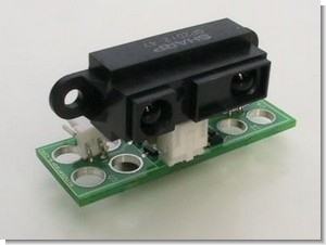
In the following photography we see the disposition of pines in the connector at the outset of the GP2D02
1.-GND
2.-Vin
3.-Vcc
4.-Vout
The device is fed putting to + 5V the pin VCC and GND to 0V(masa). The pin Vout is the exit of data in series with positive logic and levels TTL.
Vin it is the entrance with the one that will command the operation of the sensor, one must have very in account a characteristic of this pin and the fact is that the exit is to drenador open and this prohibited to put this entrance to an exit TTL or CMOS since this would cause the destruction of the entrance, alone accepts low levels and therefore to adapt it on the way out of a microcontrolador is necessary putting a diode (p.ej. : 1N4148) just as is shown subsequently:
Once we have connected the sensor remains us to send him to do a capture and to read the result , to obtain this one must continue some simple steps:
The entrance Vin in rest to to be high logical level with what the diode blocked this state and alone when a logical level be put low will be when the sensor receive the order, known this , we indicate al sensor that initiate a capture putting to logical level under the pin Vin and we will maintain the state under a time of 70mS, elapsed which we will put again Vin to logical level High. Now the sensor already has the ready data for to be transmitted and as the bus at the outset is serial we have to synchronize to know when the bits leave, the sensor manages to putting it each bit in Vout by each side of lowering of the sign Vin.
It expects of 0,2mS or less to initiate the first side of lowering.
Putting Vin to logical level low with which we initiate the first side of lowering of the sign and the sensor responds us putting the bit of greater weight “MSB” in Vout.
Reading the bit of Vout and to store it properly to complete the corresponding byte al data at the outset.
Putting Vin to high logical level.
Repeating 7 times more, the steps from 3 to 5 keeping in mind that one must delay a minimum of 1mS to read the 8 bits with what if we do it very fast the sensor will not respond properly.
Once read the 8 bits we have to expect a minimum of 1,5mS or but to be able to order al sensor another capture of distance.
It can accelerate the measure verifying when passes to high level the sign Vout while is maintained to level low Vin in the measurement start 70mS although I recommend to expect the 70mS.
It notes: As can be seen in the plan not this position the circuit oscillator of 4 MHz necessary so that function the assembly, not to be forgot to put it! (crystal of 4MHz and capacitors of 27pF)
The program uses a board of conversion calibrated to use with a white pasteboard as distant object for the measurement and sample in the LCD the distance in centimeters continuously, for other objects of different color the board can be modified easily.
MECHANICS Bumper
Description : The bumper is an electric switch of 2 positions with spring of return to the position of rest and with a lever of operation but or less long according to the chosen model.
Operation : In state of rest the common duckling (C) and that of rest (R) they are in permanent contact until the pressure applied to the lever of the bumper causes jumps the small one steel bar intern and then the contact passes from the position of rest to that of assets (A), can listen itself when the bumper changes of state, because a small click is heard, this happens almost al final Of the it traveled through of the lever.
Uses : are used for detection of obstacles by direct contact. They are not adequate for robots high speed since when they detect the obstacle already they are on top and does not give time to brake the robot.
Ideas and updates : Few improvements can have a so simple device but a good serious idea to utilize a multiplexor to put but bumpers of control in our robot and to use the control lines minimum.
MAGNETICS ULTRASOUND
Description : The ultrasonidos are vibrations of the air of the same nature that the audible sound but of a frequency but high that splits of 20 000 Hz until 5.108 Hz. Not audible these by the human ear. Lengths of wave are reached that approach the visible light.
Operation : to produce them the properties are utilized piezoelectrics of the quartz.
Uses : are utilized in the obtaining of photographic emulsions of very fine grain, in acoustic polls (detection of cracks, measurements, etc. ), Like bactericides and as the cleaners of surfaces among others.
Light LDR
Description : The LDR (Light Dependent Resistor) or dependent resistance of the light, as its own name indicates is a resistance that various its value in function of the light that impacts on its surface. Against but it be the intensity of light that impact in the surface of the LDR smaller will be its resistance and against less light impact greater will be the resistance. The external form can vary of it shown in this photo since this model in concrete is not very common but the function is the same one.
Operation :to do us a meter of environmental light or a fotocélula that light a determined process in absence or presence of light we will be able to do it of two ways, using an operational amplifier to detect and to adjust the sensibility and point in which itself unlike the exit as in the case of the CNY70 shown but up or well to do it like is shown in the following circuit, that is in base to a trigger schmitt TTL that conformed a totally compatible sign TTL For it to be applied to a microcontrolador or compatible logical door.
The circuit is comprised of a divisor of tension formed by the LDR, a resistance and a disparador trigger schmitt model investor74LS14. As the LDR various in function of the light, the sign at the outset of the divisor will also do it and when pair the threshold of shot of the trigger schmitt this Changed the state of its exit as correspond.
The thresholds of shot for the 74LS14 are of 0,9 and 1,7 volts, this means that when the sign in the entrance of the disparador surpass the 1,7 volts was taken like a 1 logical in the entrance and the exit al to be inverse took the logical level low or 0 volts, if the voltaje of low entrance under 0,9 volts was taken as a 0 logical in entrance with what the exit took a level logical 1.
The problem that was commented in the explanation of the CNY70 situates in the distance in volts between the threshold of high shot and low, that is of 0,8 volts then we imagine that if the light received in the sensor goes increasing until arriving at the 1,7 volts and to brim them this will be the point of activation but itself not al was defused to pass again by this point, since the exit circuit was not defused until descend not under the threshold of 0,9 volts, this one must have it very in account since for some cases where the levels to detect be very distant as for example to detect levels of all or nothing or light and darkness can give equal but if what is wanted is to activate some circuit in a determined level of light and to defuse it When that level no longer exist, then the circuit no longer is been worth and will be better to use the circuit based on operational amplifier in way comparator of tensions.
It notes : The integrated circuit 74LS14 arranges in its intern of 6 doors trigger schmitt negates, so one must have special care in leave not any entrance done not use al air, this is without any connection since the door began to oscillate and would be able to cause the destruction of said door, so that this happen not one must connect all the entrances to a stable logical level, normally to GND. the Exits were left like is logical al air since they will have the inverse logical level that in their entrance.
Uses : The LDR are used to detect environment light levels or monitoring of lights or flashlights, thus therefore we can create a follower of light with several LDR arranged around the robot and to do that this continue a direct light that him focus, also they can be used for Lighting the foci or lights of runway lighting of the robot in absence of light.
Ideas and upgrades: An improvement is to substitute the fixed resistance of the divisor of Volts by a variable of adequate value, to be able to adjust the threshold of shot.
Temperature LM35
Description : The LM35 is a sensor of temperature with a precision calibrated of 1ºC and a rank that covers since -55º to +150ºC.
The sensor is presented in different encapsulados but the but common is the to-92 of equal form that a typical transistor with 3 legs, two of them to feed it and the third a value of proportional tension to the temperature measured by the device delivers us. With the LM35 on the table the sideburns toward us and the letters of the encapsulado up we have that of left to right the pines are: VCC – Vout – GND.
The exit is lineal and equals to 10mV/ºC therefore:
+1500mV = 150ºC
+250mV = 25ºC
-550mV = -55ºC
Operation :For Doing us a thermometer the unique thing that need is a voltímetro well calibrated and in the correct scale so that the voltaje equivalent to temperature show us. The LM35 functions in the rank of diet understood between 4 and 30 volts.
We can connect it to an Analog/Digital converter and to treat the measure digitally, to store it or to process it with a µController or similar
Uses : The sensor of temperature can be used to compensate a device of sensitive measure to the temperature environment , to refrigerate you split delicate of the robot or well for loggear temperatures in the course of a journey of exploration.
Circuit of test : The following assembly is a meter of temperature of 4 channels
Using a PIC16F876 and a LCD to show the data although the program can be modified easily for obtain the data of temperature and to calculate with them what were necessary.
For a real measure with the converter of the Analog/Digital one a model adjustable reference tension generator has been arrangedLM336 external al pic, with which the measure of temperature will be simple and reliable. The rank of measures that bears this assembly is alone of positive temperatures and covers since 0º to +150ºC.
In the LCD the 4 channels are shown T1=RA0, T2=RA1, T3=RA2, T4=RA5.
It notes: As can be seen in the plan not this position the circuit oscillator of 4 MHz necessary so that function the assembly, not to be forgot to put it! (Crystal of 4MHz and condensers of 27pF). Forget neither to put condensers of desacoplo of 100nF among the sideburns of diet of each integrated it but close possible of these to avoid interferences by the line of diet that are very you criticize using the converter TO/D of the pic.
Adjust : There is an only adjustment that is necessary to do correctly and is referring to the tension of reference for the converter TO/D, we will cause we removing it the µController PIC of its base and measuring among the pin number 5 pertaining to “RA3 + Vref” and GND, then we will adjust through the variable resistance multivuelta (I recommend multivuelta and not normal by precision of adjustment) so that in the polímetro mark us exactly 2,56 V with which is obtained that with a TO/D conversion precision of 8 bits each 10mV dams you an increment in the byte at the outset of the converter and therefore we can represent it in a simple way without doing complex calculations.
HUMIDITY SHT11
Description : The SHT11 of the house www. sensirion. com is a sensor integrated of humidity calibrated in factory with digital exit by means of a bus series sincrono and protocol I specify. The device also has a sensor of Temperature integrated to compensate the measure of humidity depending on the temperature , in extreme cases. It counts also in its interior with a heater to avoid condensation in the interior of the capsule of measure for conditions of fog or similar where exists condensation.
Operation :The SHT11 can be fed with a rank of continuous tension understood among 2,4 to 5V and is necessary to provide it but close possible of the chip a condenser of desacoplo of 100nF between GND and VCC. In the image can be observed a Small PCB (Printed Circuit Board ) carried out al effect to harbor al SHT11 and its condenser of desaco plo, since the sensor is presented in integrated for superficial assembly LCC (Lead Chip Carrier) and is difficult of remove once soldier, so better to work with pines but standard as a SIL of 4 pines.
As it can be seen in the datasheet of the SHT11, the chip has 10 pins although alone they are used 4 of them and the others they should be welded in pads al air, simply for the subjection of the integrated.
The pin DATES corresponds on the way out data entry to command and to read the sensor and is a pin triestate for which needs a resistance of polarization to Vcc (push-up). SCK is utilized to synchronize the broadcast and does not have most minimum frequency.
Transmission Start : to be communicated with the SHT11 the first thing that one must cause is to send a Broadcast Start sequence “Transmission Start”. This it consists of putting to logical zero the line of data while SCK this to one, follow a pulse is generated low in SCK while the line DATA continues to zero and to finalize is put to 1 DATA while SCK this to 1, follow itself drop to zero also SCK and finalizes the sequence leaving the line of data and Clock in the logical states by defect, DATA in state High and SCK in state low.
The following thing will be to send a command of the following that accepts:
Command
Binary code
reserved 0000x
Measure of Temperature 00011
Measure of Humidity 00101
Reading the registy of internal state 00111
Writing the registy of internal state 00110
reserved 0101x-1110x
Generating a Reset al internal software, replacing to the values by defect the registration of state. One must expect 11mS al less after to send this command. 11110
The commands broadcast protocol this based on a complete byte or what is the same thing 8 bits , like the commands are of 5 bits so alone the remainder of bits to the left always they will be 0. For which they were sent first the 3 zeros followed by the command to complete the byte.
The SHT11 will indicate a reception validates with a pulse of ACK in the line of data that is bi-directional (do not we forget it) and will do it in the following pulse of CLK after to have completed the 8 bits of the command, therefore immediately afterwards after sending the command one must configure as entrance the port of the microcontrolador connected to DATES from the SHT11 and to generate a sign CLOCK so that the sensor send us its answer ACK and will cause putting it the line to level low since as told but up the line of data this polarized to VCC therefore always there is a 1 logical in her and what does the SHT11 is to force to 0 logical with its exit to open collector.
Sequence of measure: Supposing that already we know to send a command and for example we have sending a command “00000101” corresponding to “Measure of Humidity”, once received the ACK since the sensor one must expect to that this complete the acquisition and its measure deliver us, this is used to delaying some 55mS for a resolution at the outset of 12bits or well, some 11mS for a resolution of 8 bits. As this time of acquisition is not very exact and can vary depending on the diet of the sensor, and therefore of its internal oscillator. To avoid you expect unnecessary the sensor generates a pulse low in the line of data and thus is known that the following thing already will be data been worth , this causes verifying the line of data each x time until this pair to level low. If it is high level even not to finished and when we receive a level low will be the indication of acquisition completed and we will pass to read the measure of the sensor.
Now 8 pulses of clock in the line are generated CLK and the state of each bit is kept that the sensor returned us. The plot that returns the sensor is composed of 3 bytes, the first one corresponds to MSB the second to LSB and the third is the CRC-8 Checksum to verify that the data to arrived correct, but we can ignore it generating NACK after the arrival of the second byte (LSB). As it can be observed the data of the measure is composed of 2 bytes although as a lot the data been worth will be of 12 bits of resolution, but although we configure the sensor for a Resolution of 8 bits.. always we will read 2 bytes ignoring the MSB in this case.
Despues of each 8 bits they received the microcontroller to to generate an ACK so that the sensor know that already to received the data. This causes generating a side of ascent in CLK while DATES this to level low. After this itself continuous with the reading of another byte.
To finish the plot is generated since the microcontrolador a NACK (NoACK) this is the same thing that the ACK but instead of maintain the linea DATES to level under it we will have to put to 1 generating while this passes a side of ascent in CLK the same as before.
The sensor admits some two acquisitions or measures by second for which itself not the reading with refreshments should force over this, and neither that to say that a measure of this type does not need a so high soft drink.. serious the normal thing a measure each 5 or 10 seconds or but even.
Uses : This sensor of humidity/temperature can be used in portable weather stations, and in a robot explorer can serve to generate graphics of humidity in the places by where he passes as well as also to avoid to function or to take the adequate measures in situations of extreme climatology.
Circuit of test : The following assembly is a meter of relative humidity (without compensation of temperature) which utilizes a sensor integrated SHT11, a pic16F876 and a LCD microcontrolado.
The measure is shown by screen representing a percentage of relative humidity and is brought up to date each 2 seconds.
Source: x-robotics.com Sensor Circuits alternative link:


Simple Circuits Book a 555 Timer Application
Talking Electronics Sites previously shared the new book The 200 pieces prepared for transistor circuits I mentioned. Author of this type continues to kitaplarıpaylaş free.
Many of the circuits simple circuits 555 in the book is set up with very few elements oscillators, timing, LEDs, motor control and you have to practice a lot more
555 timer circuits