M5218AP solid bass filter circuit, LM741 opamp amplfier built on symmetrical power supply + 56 – 56 volts symmetrical bass filter section 15 volt zener regulated by whether they have been power supply.
Stereo 50kω … 200hz frequency setting potentiometer VR1 is done with the 40 1k potentiometer VR3 guess the quiescent current is adjusted to be between 30 to .40 m. The recommended value for the filter capacitor in the supply circuit to be used 10000uF 63 volt transformer voltage volts AC 150W 2X40 If you want the “Sub Bass” filter section you can use a different amp circuits.
100W Bass Subwoofer Amplifier Schematic PCB


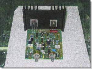
250W Amplifier Circuit Modfet 2SJ162 2SK1058
A quality 250w MOSFET amplifier circuit supply voltage + 67 – 67 volts, 134 volts symmetrical assembly and testing stages of testing, be careful. Pcb circuit drawings, layout and bill of materials are available. Output MOSFET 2SK1058 3 (N-Channel) 2SJ162 (P-Channel) drive solid MJ, BC-type transistors consist of.
50k VR1 potentiometer can adjust sound settings for the desired level VR2 470Ω potentiometer for setting the quiescent current adjustable from 60mA….100mA