The basic component is the operational amplifier MCP6001 acting as a comparator. It has a number of advantages that were used in this project:
Small supply voltage (1.8 to 6 V).
Low power consumption (typically 100 μA).
Rail-to-Rail output.
Small housing (SOT23-5).
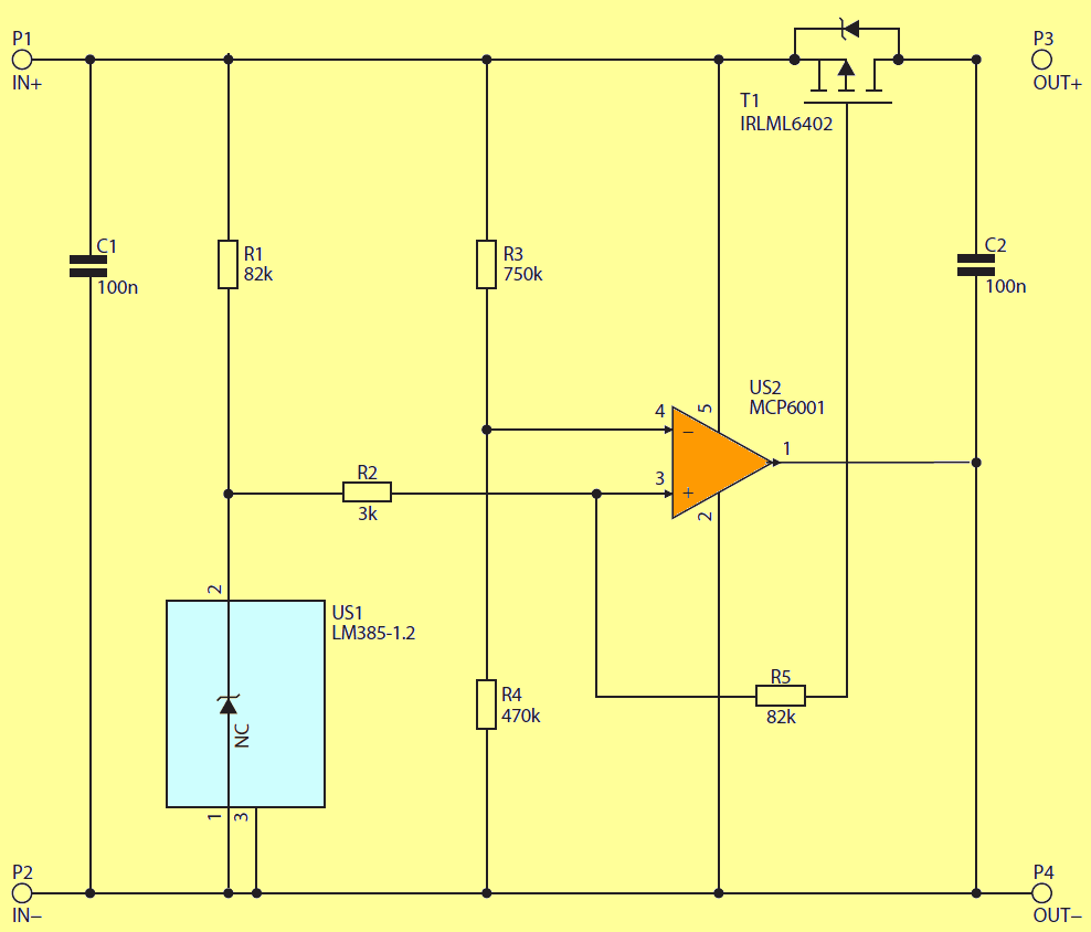
Its output directly controls the gate of the IRLML6402 MOSFET-P transistor, which switches on the load. The role of the reference voltage source is made by the LM385-1.2 system providing a stable voltage of 1.235 V. The resistor R1 causes the current flowing through it to be about 28 μA at a voltage of 3.5 V.
The minimum value of this current has been determined by the manufacturer for 10 μA, so the correct work of the element is ensured in a wide temperature range. The elements surrounding the US2 system set the thresholds for switching on and off the load, in particular the resistor R5, which causes them to be extended.
The difference between them must be large enough so that the system does not fall into oscillations caused by the disconnection of the load with high power consumption from the cell with a significant internal resistance. Resignation from any parameter adjustment by the user enabled miniaturization of the device. Reading of catalog notices of various cells showed that the minimum voltage to which the cell can be unloaded without fear of its damage, is in the range 2.7 … 3 V.
Battery Protection Circuit Scehematic
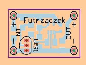
It follows that the 3 V shutdown threshold will be suitable for all cells. In turn, the maximum current consumed is limited by the transistor and is about 2 A depending on the ambient temperature. The battery protection circuit is assembled on a single-sided PCB measuring 26 mm × 15 mm. The device does not require any start-up activities. The following values were measured in the model copy:
switching threshold: 3.06 V,
switch-off threshold: 3.38 V,
voltage drop at 1 A current consumption by load: 67 mV (UZAS = 3.5 V),
power consumption without load: 140 μA at UZAS = 3.5 V and 130 μA at UZAS = 3 V.
The plate can be protected against the influence of environmental factors by covering it with varnish and pressing into a section of a heat-shrinkable tube.
![]()
FILE DOWNLOAD LINK LIST (in TXT format): LINKS-26151.zip


Portable Mosquito Repellent Circuit
Portable Mosquito Repellent Circuit
As you know, piezoelectric transducers tricycles have a capacitive character of the load. Therefore, appropriate is required control. On the one hand, the transmitter is fed directly from the US2 generator output to construction that I used the 555 tajmer in the CMOS version. The other side of the transducer, on the other hand it is connected to the output of the reverse transistor-like phase inverter signal. In this way I baked two birds with one stone. I ensured proper control the piezo element and built a bridge circuit that ensures maximum utilization of the supply voltage the resulting system and thus the maximum power delivered to the transducer. I was not tempted to fun with the coil increasing the tension because the problem of mosquitoes I decided to solve locally around oneself. Let others also get a little revenge and build Mosquito Repellent Circuit themselves. If they will not they could come to me and then a little
The anti-parallel stage works in an inverted system in relation to what is found in the power terminals. Simply put emitters transistors T1 and T2 are connected to the power supply and to the ground. When there is a state at the US1 output the high transistor T1 is clogged and the transistor T2 is open. So the transmitter has a full voltage supply.
Resting frequency Generator operation is set to 38 kHz and can be changed by inserting the R5 o resistor in the system another value. In the modulation system, I used the US1B operating amplifier operating as are-generator I was taking on 2 kHz according to the instructions of a mosquito literalist. Frequency of work the relaxation generator depends on several factors, in fact all the elements from which it folds except for the operational amplifier. Of course, the steady influence has the greatest impact time R1, C1. The R2 ÷ R4 resistors have a smaller impact.
Mosquito Repellent Circuit Schematic
Circuit de protection de la batterie Li-Ion ou Li-Po
Le composant de base est l’amplificateur opérationnel MCP6001 faisant office de comparateur. Il présente un certain nombre d’avantages qui ont été utilisés dans ce projet:
Petite tension d’alimentation (1,8 à 6 V).
Faible consommation d’énergie (généralement 100 μA).
Sortie rail à rail.
Petit boîtier (SOT23-5).
Sa sortie contrôle directement la grille du transistor MOSFET-P IRLML6402, qui active la charge. Le rôle de la source de tension de référence est assuré par le système LM385-1.2 fournissant une tension stable de 1,235 V. La résistance R1 fait que le courant qui la traverse est d’environ 28 μA à une tension de 3,5 V.
La valeur minimale de ce courant a été déterminée par le fabricant pour 10 μA, de sorte que le bon fonctionnement de l’élément est assuré dans une large plage de températures. Les éléments entourant le système US2 fixent les seuils d’allumage et d’extinction de la charge, notamment la résistance R5, ce qui entraîne leur extension.