As you know, piezoelectric transducers tricycles have a capacitive character of the load. Therefore, appropriate is required control. On the one hand, the transmitter is fed directly from the US2 generator output to construction that I used the 555 tajmer in the CMOS version. The other side of the transducer, on the other hand it is connected to the output of the reverse transistor-like phase inverter signal. In this way I baked two birds with one stone. I ensured proper control the piezo element and built a bridge circuit that ensures maximum utilization of the supply voltage the resulting system and thus the maximum power delivered to the transducer. I was not tempted to fun with the coil increasing the tension because the problem of mosquitoes I decided to solve locally around oneself. Let others also get a little revenge and build Mosquito Repellent Circuit themselves. If they will not they could come to me and then a little
The anti-parallel stage works in an inverted system in relation to what is found in the power terminals. Simply put emitters transistors T1 and T2 are connected to the power supply and to the ground. When there is a state at the US1 output the high transistor T1 is clogged and the transistor T2 is open. So the transmitter has a full voltage supply.
Resting frequency Generator operation is set to 38 kHz and can be changed by inserting the R5 o resistor in the system another value. In the modulation system, I used the US1B operating amplifier operating as are-generator I was taking on 2 kHz according to the instructions of a mosquito literalist. Frequency of work the relaxation generator depends on several factors, in fact all the elements from which it folds except for the operational amplifier. Of course, the steady influence has the greatest impact time R1, C1. The R2 ÷ R4 resistors have a smaller impact.
Mosquito Repellent Circuit Schematic
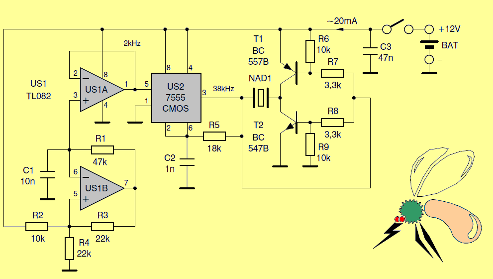
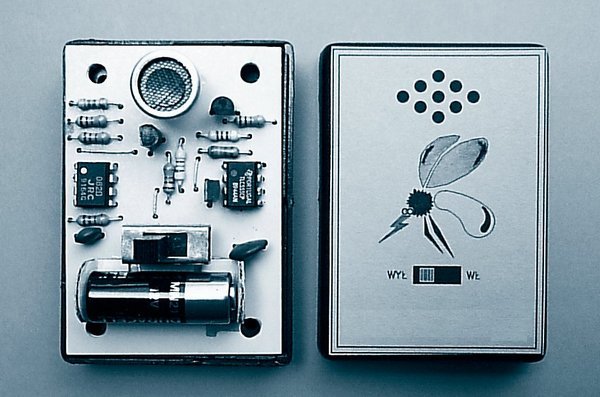
The latter, however, affect the amplitude of the triangular waveform occurring on the capacitor C1. At the output of the amplifier operational US1B receives an unnecessary rectangular course here. I have chosen the elements’ values in such a way that the triangular triangle (value interpass) has a value of approx. 2V with a constant component of approx. 8 V. This voltage is I worked for the second US1A amplifier working as a voltage repeater. In this way I have separated the US1B generator from the load, which is the modulating input of the 555 system. the tajmer frequency changes cyclically around the selected 38 kHz central frequency. The system is powered by a miniature 12V battery type MN 21. Battery
FILE DOWNLOAD LINK LIST (in TXT format): LINKS-26154.zip


Protection Circuit of Li-Ion or Li-Po Battery
Protection Circuit of Li-Ion or Li-Po Battery
The basic component is the operational amplifier MCP6001 acting as a comparator. It has a number of advantages that were used in this project:
Small supply voltage (1.8 to 6 V).
Low power consumption (typically 100 μA).
Rail-to-Rail output.
Small housing (SOT23-5).
Its output directly controls the gate of the IRLML6402 MOSFET-P transistor, which switches on the load. The role of the reference voltage source is made by the LM385-1.2 system providing a stable voltage of 1.235 V. The resistor R1 causes the current flowing through it to be about 28 μA at a voltage of 3.5 V.
The minimum value of this current has been determined by the manufacturer for 10 μA, so the correct work of the element is ensured in a wide temperature range. The elements surrounding the US2 system set the thresholds for switching on and off the load, in particular the resistor R5, which causes them to be extended.
The difference between them must be large enough so that the system does not fall into oscillations caused by the disconnection of the load with high power consumption from the cell with a significant internal resistance. Resignation from any parameter adjustment by the user enabled miniaturization of the device. Reading of catalog notices of various cells showed that the minimum voltage to which the cell can be unloaded without fear of its damage, is in the range 2.7 … 3 V.
Battery Protection Circuit Scehematic
Circuit portable anti-moustiques
Comme vous le savez, les tricycles transducteurs piézoélectriques ont un caractère capacitif de la charge. Par conséquent, un contrôle approprié est requis. D’une part, l’émetteur est alimenté directement de la sortie du générateur US2 à la construction que j’ai utilisé le 555 tajmer dans la version CMOS. L’autre côté du transducteur, d’autre part, il est connecté à la sortie du signal inverseur de phase de type transistor inverse. De cette façon, j’ai cuit deux oiseaux avec une pierre. J’ai assuré un bon contrôle de l’élément piézoélectrique et construit un circuit en pont qui assure une utilisation maximale de la tension d’alimentation du système résultant et donc la puissance maximale délivrée au transducteur. Je n’ai pas été tenté de m’amuser avec la bobine augmentant la tension car le problème des moustiques j’ai décidé de le résoudre localement autour de soi. Laissez les autres aussi se venger et construisez eux-mêmes un circuit anti-moustiques. S’ils ne le font pas, ils pourraient venir vers moi et puis un peu