LED Heart Circuit PIC16F628
ATmega88 led heart circuit (smd led effect), Led Heart Circuit Music Box RGB Led Effect, RGB Led Heart Circuit PIC 12F629 Mood Light, 30 Led LED Heart circuit made with..
PIC circuits, PIC projects have been realized with microchip controllers of Microchip company.
ATmega88 led heart circuit (smd led effect), Led Heart Circuit Music Box RGB Led Effect, RGB Led Heart Circuit PIC 12F629 Mood Light, 30 Led LED Heart circuit made with..
A device used to monitor water oil temperatures and battery charge voltage for automotive. The heart of the circuit is PIC16F628 microcontroller car temperature measurement is provided by 2 DS18B20..
Whistle key finder device. Its operation is basically a keychain that responds with a beep-beep sound when we whistle at the right frequency. A miniature electret microphone captures the whistle..
15 channel Vu meter circuit with peak hold or peak hold feature. It can be done with PIC16F1508, PIC16F1509, microcontrollers. I powered the PIC outputs with mosfet and drove strip..
Arcade Joystick is a DIY USB keyboard encoder made with PIC18F24K50 microcontroller. It allows you to create a USB arcade stick for example or use it in a special MAME..
The password electronic lock circuit PIC16F628A can store up to 128 users’ passwords. Users can change their passwords whenever they want. PIC16F628 and external Eeprom 24c08 are used to store..
The aim is to make a simple and at the same time effective device that will count the number of people entering and exiting rooms with a single entrance door…
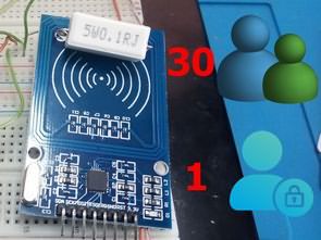
A project using RFID-RC522 module and PIC16F628A to perform access control with RFID Key cards. Adapted from Arduino “AcessControl” software. The PIC16F628A software is written in CCS C to work..
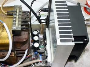
Voltage adjustment from 0.1V to 25V with “+” and “-” buttons; When the “+” and “-” buttons are held down, a slow change begins at 0.1V, after 2 seconds the..
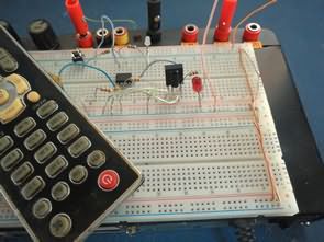
I tested another combination lock circuit. The function of the system is to receive the signals from the infrared receiver and compare them with the values previously stored in the..