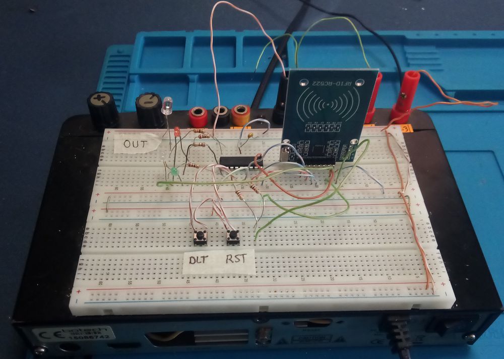
A project using RFID-RC522 module and PIC16F628A to perform access control with RFID Key cards. Adapted from Arduino “AcessControl” software. The PIC16F628A software is written in CCS C to work without SPI hardware.
The RFID-RC522 module performs the entire radio frequency communication process (13.56 Mhz) with RFID tags. An RFID tag is an electronic tag that can be found inside cards, keychains, or stickers. The microcontroller accesses the information in the RFID-RC522 module using the SPI protocol. 5 pins are required to work in this protocol: RESET, MOSI, MISO, SLK and SDA
Since PIC16F628A does not have internal hardware with SPI function, it was implemented using software (bit banging). Additionally, deletion and reset operations are performed with 2 buttons. One of the buttons is used to reset the microcontroller and the other to delete the data recorded in the PIC16F628 eeprom. There are two modes of deletion.
During installation and in normal operating mode. In the first mode (setup), it is used to delete all tags registered in the EEprom of the microcontroller, including the main tag. The second mode (normal mode deletion) is used to delete the main tag only.
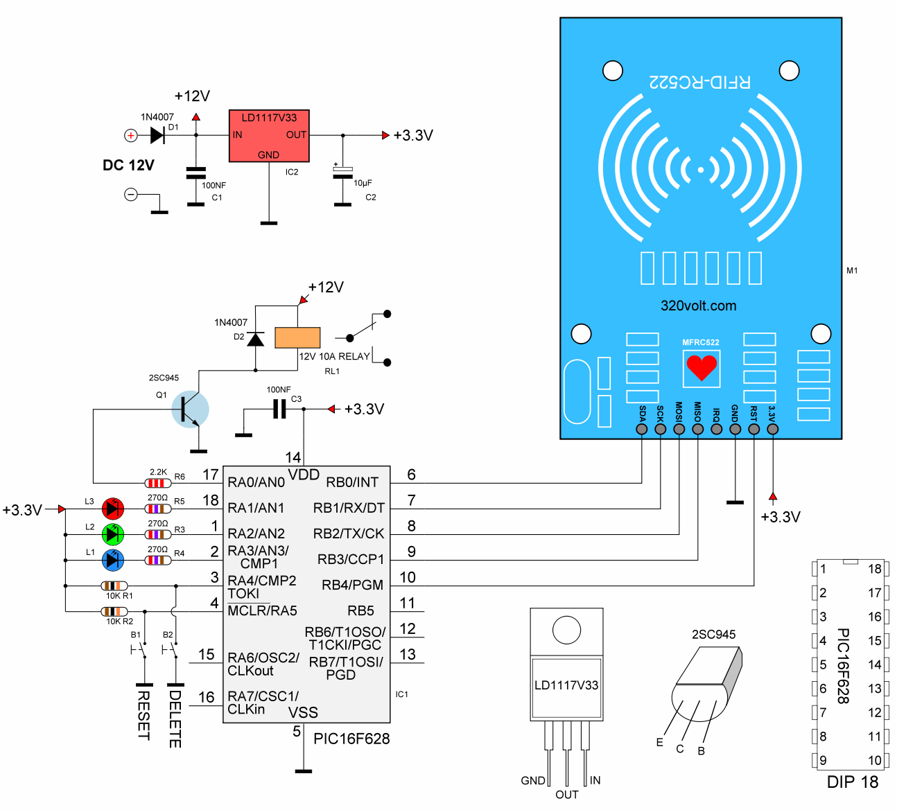
PIC16F628A pin number 17 is used for output, the relay is operated with the transistor connected to this pin, door lock etc. are connected to the relay contacts. can be connected. LED indicators are used for status information.
3 LEDs notify the user of various states:
Blue LED – indicates normal use mode (solid) and programming mode (blinking).
Red LED – illuminates for 1 second to indicate that authentication has been rejected (in normal mode) or the card has been deleted (in programming mode).
Green LED – indicates allowed access (in normal mode) or card registered in the eeprom (in programming mode) and illuminates for 1 second.
The circuit can be powered by a 12 volt (DC) source. The voltage of the RFID-RC522 module is obtained using the LD1117V33 3.3V regulator integrated.
RFID-RC522 PIC16F628A Circuit Diagram
RFID Settings
When the PIC16F628A software is loaded and the circuit is run, the Blue LED blinks continuously. RFID card or key fob. Pass it very close to the RFID-RC522 module. Once saved you will see the blue LED stop blinking and stay on solid. This first tag (card, key) saved will be the ‘master, management tag’. It will be used to save or delete other secondary tags.
Then save the other tags by following these steps:
1) Pass the main tag through the RFID-RC522 module. The blue LED will start flashing. This indicates it is in ‘programming mode’.
2) Pass the label you want to save. The green LED will light for 1 second.
Note: If it has been saved to EEprom before, it will be deleted. In this case, the red LED will light for 1 second, indicating that it has been deleted.
4) Continue saving other labels in this way.
5) When you finish saving the tags, show the main tag and exit the programming mode. Then the blue LED will stop blinking and stay on solid (it has entered normal mode).
To remove access for a tag, follow these steps:
1) Pass the main tag through the RFID-RC522 module. The blue LED will flash.
2) Pass the label to be removed. The red LED will light for 1 second.
3) Pass the main tag. The blue LED will be on continuously.
4) Check the removed tag. The red LED should light for 1 second (access denied).
To remove all tags in EEprom, including the main tag:
1) Press and hold both RESET and DELETE Buttons
2) Release the RESET Button and hold down the DELETE button. Wait until the red LED starts flashing. Then release the DELETE button. The blue LED will then start flashing (successful deletion).
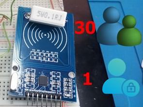
Since the EEprom of PIC16F628A is only 128 bytes, it is possible to save 30 secondary tags and one main tag.
RC522 RFID Reader Module
RC522 is a multi-communication RFID module for Arduino modules and other microcontrollers. RC522 is known as MFRC-522 because of its NFX semiconductor microcontroller. The module allows developers to use it with other SPI, I2C and UART-based microcontrollers. The RC522 module operates at a frequency of 13.56 MHz and can act as a reader and writer for UID/RFID cards. RFID cards communicate with the module at short distances via radio frequency using mutual induction technique. In most security and commercial products, the module is effective because errors and problems with RFID tags can be detected by the module.
There are only two types of pins in this module. The first is power and the second is communication pins. Therefore, even though the device has a microcontroller chip on it, it only works as RFID. The onboard microcontroller does not make the module a standalone device.
RC522 Pins
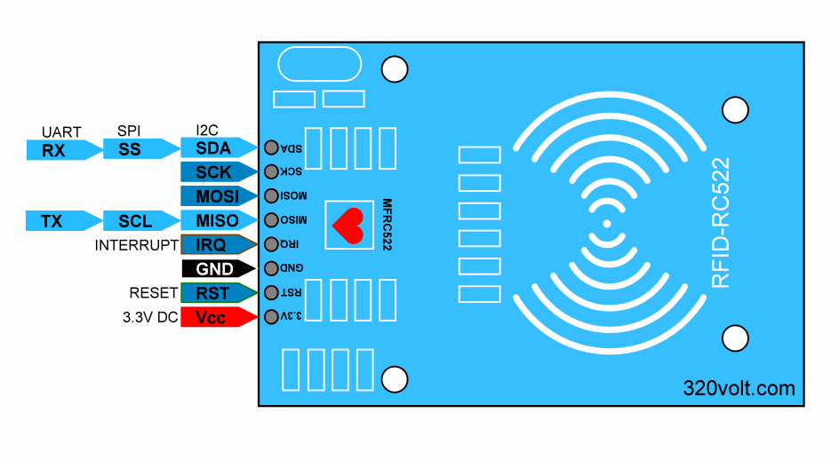
All pins of MFRC/RC522 RFID card Reader are:
VCC Power pins are VCC. In some versions of RC522, this pin is indicated as 3V3 instead of VCC on the module.
RST is a reset pin for the Module. It is used to reset the device in case of an error when the device does not respond.
GND Chassis helps to create common GND with every external device like power supply, microcontroller or arduino.
SPI and UART Communication Pins
IRQ The device can go into sleep mode to save power. IRQ helps wake up.
MISO SCL TX This pin is connected to Arduino/Microcontrollers for SPI communication. Transfers data from the module to Arduino. The MISO pin can also be used for other functions instead of SPI. It can also interface with I2C for clock pulse and UART Serial for Data transfer from the module.
MOSI MOSI (Master Out Slave In) is the data input pin of the RFID module in SPI communication
SCK SCK pins help send the clock pulse in SPI communication.
SDA RX SS pin is the chip enable pin in SPI communication. It receives the signal when it needs to perform SPI communication.
The SS pin on RFID can be used as a second pin (SDA) for I2C communication.
It also receives data during UART communication.
RC522 RFID Reader Features
RFID RC522 uses mutual induction to activate cards and 13.56MHz for data transfer.
RFID Cards can be used at a maximum distance of 5cm from both sides of the module.
Only 3.3V is required to activate the device.
Automatic sleep mode makes it a less power consumption module.
The module has three kinds of communication (UART, SPI, I2C). Therefore, it can be used with almost any microcontroller or device on the market.
RFID cards and reader (RC522) can transfer data at up to 10Mb/s.
What is RFID technology and how does it work?
RFID or radio frequency identification system consists of two main components: a tag attached to the object to be identified and a reader that reads the tag.
The reader consists of a radio frequency module and an antenna that produces a high-frequency electromagnetic field. The tag is usually a passive device (no battery). It consists of a microchip that stores and processes information and an antenna used to receive and transmit signals.
When the tag is brought close to the reader, the reader creates an electromagnetic field. This causes electrons to move across the tag’s antenna and then power the chip.
The chip then responds by sending the stored information back to the reader in the form of another radio signal. This is called backscatter. The reader detects and interprets this backscatter and sends the data to a computer or microcontroller.