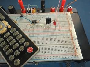
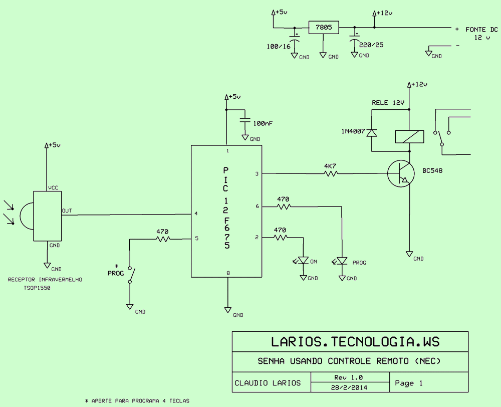
I tested another combination lock circuit. The function of the system is to receive the signals from the infrared receiver and compare them with the values previously stored in the EEprom of the PIC12F675. After receiving the 4-digit password, it compares the lock activation output and outputs. To set the password, simply press the ‘Prog’ button and when the ‘Prog led’ lights up, you can set the 4-digit password. While doing this, the ‘Prog led’ will flash and the output will be active when the password is confirmed.
To enable continuous mode output, add // to the beginning of the “#define pulsado” code in the source C code, so that the output will be one time at the specified time.
Logically, the remote control code system is limited by the view range of the remote control relative to the receiver. Whoever is going to use the device will need to point it directly at the receiver. The protocol used in this review is LG, SEMP, ELSYS etc. is the ‘NEC’ used by companies.
Controlled Combination Lock Circuit Diagram
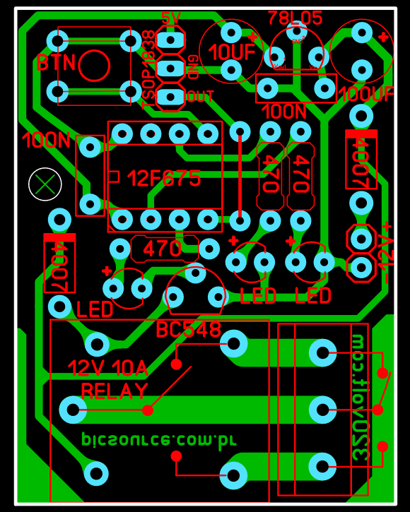
All files of pcb, schematic, code of Remote Controlled Electronic Combination Lock circuit: remote-keylock.rar pass: 320volt.com


