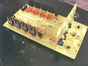
Quality pcb printed circuit design with two amp circuit I share 180 watt amp circuits used in power output transistors 2sa1943 2sc5200 supply voltage + -45 volts DC P-CAD 2001 prepared by the PCB and P-CAD 2001 Schematic prepared by the schema file there.
450 watt amp features the same count in the circuit and transistor supply voltage is higher than the number
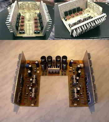
In this UMZCH used modular design, so called.it is divided into two logically completed block: amplifier output voltage and powerful repeater. This allows, if necessary, or for the sake of the experiment apply different circuitry data nodes.You can mix tube amplifier output voltage and transistor cascade. Similarly, the output cascade can be executed as a bipolar transistor, and at the MOSFET
Source: http://www.sibaudio.ru/ Professional Amplifier Circuits Alternative link:


PIC16F628 RGB LED Control Circuit
RGB LED control circuit 16F628 microcontroller based on the software prepared by JAL. Source code and circuit diagrams are available. According to information from the computer via serial port LEDs working with Visual Basic code for the application of resources given the necessary programs.
RGB control circuit diagram
Professionelle Verstärkerschaltungen 450W 180W
Hochwertiges Leiterplatten-Leiterplattendesign mit zwei Ampere-Schaltkreisen, die sich 180-Watt-Ampere-Schaltkreise teilen, die in den Ausgangsleistungstransistoren 2sa1943 und 2sc5200 verwendet werden.
450-Watt-Ampere weist die gleiche Zählung in der Schaltung auf und die Transistorversorgungsspannung ist höher als die Anzahl
Professionelle Verstärkerschaltungen 450W 180W 2cs5200 2sa1943 450w
In diesem von UMZCH verwendeten modularen Aufbau ist das so genannte .it in zwei logisch vervollständigte Blöcke unterteilt: Verstärkerausgangsspannung und leistungsfähiger Repeater. Dies ermöglicht, falls erforderlich, oder zu Versuchszwecken, unterschiedliche Schaltungsdatenknoten anzuwenden. Sie können die Ausgangsspannung des Röhrenverstärkers und die Transistorkaskade mischen. Ebenso kann die Ausgangskaskade als Bipolartransistor und am MOSFET ausgeführt sein