RGB LED control circuit 16F628 microcontroller based on the software prepared by JAL. Source code and circuit diagrams are available. According to information from the computer via serial port LEDs working with Visual Basic code for the application of resources given the necessary programs.
RGB control circuit diagram
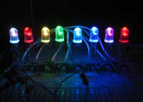
This code is for a simple RGB LED controller for 8 LEDs using a PIC16F628. It is controlled by sending 3 bytes to the internal USART for the red, green, and blue color channels. The operation is very simple and so is the wiring. The PIC selects each LED then turns on/off the respective colors then goes to the next LED. Because of persistence of vision, the eye sees the LEDs as all being on at the same time.
Source: semifluid.com/?p=12 PIC16F628 RGB LED Control Circuit Alternative link:


12V to 16V DC DC Converter Circuit MAX643
DC to DC Converter Adjustable CMOS Step-Up Switching regulator MAX643 circuit made with integrated MOSFETs supported by irf540 power output increased 45 kHz operating frequency of the circuit used in the circuit 0.8mm wire on the coil ring toroidal core 40 to be wound round
MAX643 DC DC Converter
PIC16F628 RGB-LED-Steuerkreis
RGB LED Steuerschaltung 16F628 Mikrocontroller basierend auf der von JAL erstellten Software. Quellcode und Schaltpläne sind verfügbar. Laut Angaben des Computers über die serielle Schnittstelle arbeiten LEDs mit Visual Basic-Code für den Einsatz von Ressourcen mit den erforderlichen Programmen.
RGB-Steuerkreisdiagramm
Dieser Code bezieht sich auf einen einfachen RGB-LED-Controller für 8 LEDs unter Verwendung eines PIC16F628. Sie wird gesteuert, indem 3 Bytes für die roten, grünen und blauen Farbkanäle an den internen USART gesendet werden. Die Bedienung ist sehr einfach und auch die Verkabelung. Der PIC wählt jede LED aus und schaltet die jeweiligen Farben ein / aus und geht dann zur nächsten LED. Aufgrund des anhaltenden Sehvermögens sieht das Auge, dass alle LEDs gleichzeitig leuchten.